
Why Pole Building Electrical Wiring Fails Inspection
Post-frame construction, commonly known as pole barns, has surged in popularity for workshops, barndominiums, and agricultural storage. However, the hybrid nature of these structures—combining pressure-treated wood, exposed steel trusses, and direct earth contact—creates unique electrical challenges. When it comes to pole building electrical wiring, local electrical inspectors are notoriously strict. The open framing and lack of traditional drywall mean that wiring methods considered safe in a residential home can become immediate code violations and fire hazards in a post-frame building.
From an inspection and compliance perspective, passing the rough-in and final electrical inspections requires a deep understanding of the National Electrical Code (NEC), specifically regarding physical protection, grounding electrode systems, and feeder sizing. This guide breaks down the exact NEC compliance requirements you need to know to avoid red tags and ensure a safe, code-compliant installation in 2026.
The Grounding Electrode Misconception (NEC Article 250)
The single most common reason pole building electrical wiring fails the initial inspection is improper grounding. Many builders and DIYers mistakenly believe that because the pressure-treated wooden poles or steel posts are buried directly into the earth, the building's structural frame can serve as the grounding electrode. This is a direct violation of NEC Article 250.
Under NFPA NEC guidelines, a grounding electrode must be a recognized, conductive body intentionally installed to connect to the earth. Metal poles driven into dirt do not meet the criteria for a grounding electrode under NEC 250.52.
Compliant Grounding Solutions for Post-Frame Structures
To pass inspection, your subpanel must be tied to a proper grounding electrode system. You have two primary compliant options:
- Concrete-Encased Electrode (Ufer Ground): If your pole building has concrete footings or a slab, NEC 250.52(A)(3) requires you to use a concrete-encased electrode. This consists of at least 20 feet of bare copper wire (minimum 4 AWG) or steel reinforcing bar (minimum 1/2-inch diameter) encased in at least 2 inches of concrete in direct contact with the earth. Pro Tip: You must stub this wire out of the footing before the concrete pour; retroactively adding a Ufer ground is impossible.
- Ground Rods: If no concrete footing exists, you must install ground rods per NEC 250.52(A)(5). You are required to drive at least two 5/8-inch copper or copper-clad steel rods, each at least 8 feet long, into the earth. Crucially, they must be spaced at least 6 feet apart. The only exception is if a fall-of-potential test proves the first rod has a resistance to ground of less than 25 ohms, but most inspectors will simply require the two-rod setup without testing.
"In my 15 years as a municipal inspector, 80% of the red tags I issue on pole barns are for missing or improperly bonded grounding electrodes. You cannot just clamp a ground wire to a buried steel post and call it a day."
— Senior Electrical Inspector, Midwest Jurisdiction
Feeder Sizing and Voltage Drop Calculations
Pole buildings are often situated 100 to 300 feet away from the main service panel. This distance makes voltage drop a critical compliance and performance issue. While the NEC recommends a maximum of 3% voltage drop on branch circuits and 5% total for feeder and branch circuits combined (NEC 310.15(B)), undersized feeders will cause motors (like air compressors and welders) to overheat and fail.
Furthermore, NEC 250.32(B)(1) mandates a strict 4-wire feeder system for outbuildings: two ungrounded (hot) conductors, one grounded (neutral) conductor, and one equipment grounding conductor (EGC). The neutral and ground must be completely isolated at the subpanel.
2026 Feeder Sizing Matrix (240V Single-Phase)
The following table outlines minimum wire sizing for a 100A or 200A subpanel, accounting for a 3% voltage drop limit at standard distances. Material costs reflect early 2026 market averages for THWN-2/XHHW-2 conductors pulled through PVC conduit.
| Distance from Main Panel | Subpanel Ampacity | Copper Wire Size (THWN-2) | Aluminum Wire Size (XHHW-2) | Est. 2026 Conductor Cost |
|---|---|---|---|---|
| 50 Feet | 100 Amp | #3 AWG | #1 AWG | $250 - $320 |
| 100 Feet | 100 Amp | #1 AWG | 2/0 AWG | $480 - $600 |
| 150 Feet | 200 Amp | 3/0 AWG | 4/0 AWG | $950 - $1,200 |
| 250 Feet | 200 Amp | 350 kcmil | 350 kcmil | $2,100 - $2,600 |
Note: Always calculate the Equipment Grounding Conductor (EGC) size separately based on NEC Table 250.122. For a 200A feeder, you need a minimum #6 AWG copper or #4 AWG aluminum ground wire, regardless of voltage drop calculations.
Top 4 NEC Code Violations Flagged During Pole Barn Inspections
Beyond grounding and feeder sizing, the physical routing of wires inside the post-frame structure is heavily scrutinized. Inspectors look for specific wiring methods that can withstand the harsh, exposed environment of a pole building.
1. Exposed NM-B (Romex) Cable on Surface Framing
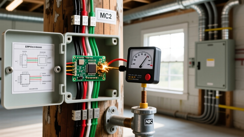
Running standard nonmetallic-sheathed cable (NM-B/Romex) stapled directly to the exposed face of wooden poles or girts is a guaranteed inspection failure. NEC 334.15(B) requires cables to be protected from physical damage. In a pole barn, where tools, lumber, and vehicles are constantly moving, exposed NM-B is highly vulnerable. The Fix: Run wires through EMT (Electrical Metallic Tubing), IMC (Intermediate Metal Conduit), or use MC (Metal-Clad) cable, which features an interlocking aluminum armor that satisfies physical protection requirements.
2. Missing GFCI Protection in Outbuildings
Under NEC 210.8(A)(2) and (G), all 125-volt, single-phase, 15- and 20-ampere receptacles installed in outbuildings, garages, and accessory buildings must have Ground-Fault Circuit-Interrupter (GFCI) protection. Inspectors will test every receptacle with a GFCI tester during the final walkthrough. Failing to use GFCI breakers or GFCI receptacles will result in an immediate fail.
3. Improper Subpanel Bonding
As mentioned, the main bonding jumper (the green screw or strap) must be removed from the subpanel. In a main service panel, the neutral and ground bars are bonded together. In a pole building subpanel, they must remain strictly isolated. If a neutral current returns via the grounding path, it can energize the building's metal trusses and siding, creating a severe shock hazard.
4. Unsecured and Unsupported Conduit
When using PVC or EMT conduit along the horizontal girts of a pole barn, NEC 358.30 and 352.30 dictate strict support intervals. PVC conduit must be secured within 3 feet of every box and at intervals not exceeding 3 feet (for 1/2" to 1" pipe) or 5 feet (for 1-1/4" and larger). Inspectors frequently flag long, sagging horizontal runs that lack proper strapping.
Trenching and Underground Service Conductors
If your pole building requires a new underground feeder from the main house, trenching compliance is governed by NEC Article 300.5. Agricultural and rural environments often feature rocky soil or high water tables, making proper burial depth and backfill procedures critical for passing inspection and ensuring longevity. According to University of Minnesota Extension guidelines on agricultural electrical systems, improper trenching is a leading cause of premature wire failure due to rock damage and frost heave.
Minimum Burial Depths (NEC Table 300.5)
| Wiring Method | Minimum Burial Depth | Inspector Notes |
|---|---|---|
| Direct Burial UF-B Cable | 24 Inches | Must be protected by conduit from trench bottom to 8 ft above grade. |
| PVC Conduit (Schedule 40/80) | 18 Inches | Schedule 80 required where emerging from ground or subject to damage. |
| Rigid Metal Conduit (RMC) | 6 Inches | Requires 2 inches of concrete encasement if under driveways. |
The Warning Tape Rule: NEC 300.5(D) requires a continuous warning ribbon (typically bright yellow or red) to be placed in the trench at least 12 inches above the underground electrical installation. If an inspector digs a test hole and does not find the warning tape, they will fail the trench inspection before you are even allowed to backfill.
The Rough-In Inspection Checklist
Before calling your local authority having jurisdiction (AHJ) for the rough-in inspection, verify your pole building electrical wiring against this compliance checklist:
- Panel Isolation: Subpanel neutral bar is floating (isolated from the metal enclosure); ground bar is securely bonded to the enclosure.
- 4-Wire Feed: Two hots, one neutral (white/gray), and one dedicated equipment ground (green/bare) are present and correctly terminated.
- Grounding Electrode: Two ground rods driven and spaced 6+ feet apart, OR a Ufer ground stubbed out and properly clamped using an acorn clamp rated for direct burial.
- Physical Protection: No exposed NM-B cable. All branch circuits routed through EMT, IMC, RMC, or MC cable.
- Box Fill Calculations: Junction boxes and panel gutters are not overfilled. NEC 314.16 box fill volumes are respected.
- Sealing Conduits: If conduit runs from an underground trench directly into the subpanel, the conduit end is sealed with duct seal or expanding foam to prevent moisture and radon gas from entering the panel.
- Working Clearance: NEC 110.26 requires a minimum 30-inch wide, 36-inch deep, and 6.5-foot high clear working space in front of the subpanel. Do not frame shelving or storage closets in this zone.
For further safety standards regarding commercial and agricultural outbuildings, always cross-reference your plans with OSHA's electrical safety guidelines, especially if the pole building will be used for employee workspaces or commercial manufacturing. By treating the unique structural aspects of post-frame buildings with the respect they demand, you will ensure a smooth inspection process and a safe, durable electrical system for decades to come.