
Electric Heater Thermostat Wiring Troubleshooting Guide
When an electric baseboard heater, wall convector, or radiant ceiling panel fails to produce heat, the thermostat and its associated wiring are the most common culprits. Troubleshooting electric heater thermostat wiring requires a methodical approach, a solid understanding of system topologies, and strict adherence to electrical safety protocols. Whether you are dealing with a legacy mechanical bimetallic switch or a modern Wi-Fi-enabled line-voltage smart thermostat, this guide provides the exact diagnostic steps, multimeter readings, and failure modes you need to restore your heating system.
Critical Safety: Lockout and Verification
Electric space heaters typically operate on 240-volt or 120-volt line-voltage circuits. A shock from a 240V circuit can be lethal. Before removing any thermostat cover or wire nut, you must verify zero energy state. According to OSHA's Lockout/Tagout standards, simply flipping a wall switch or relying on a thermostat's "off" setting is insufficient for safe electrical work.
- Locate the Breaker: Identify the dedicated double-pole breaker (for 240V) or single-pole breaker (for 120V) in your main service panel.
- Lockout/Tagout: Switch the breaker to the OFF position and apply a physical lock or tag to prevent accidental re-energization.
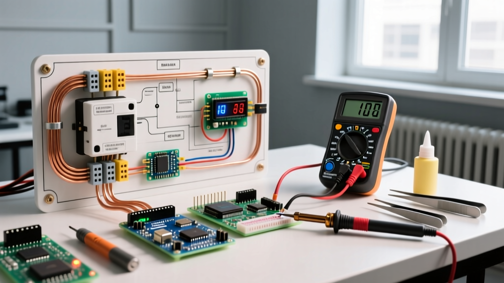
- Verify with a CAT III Multimeter: Use a True RMS multimeter (such as the Fluke 117, approx. $170, or Klein Tools MM400, approx. $50). Test across the line and load terminals, and from each terminal to ground, to confirm 0V before touching any conductors.
Understanding System Topologies
Before testing, identify which of the two primary electric heater thermostat wiring architectures you are troubleshooting. Misidentifying the system type leads to incorrect multimeter testing and potential short circuits.
1. Line-Voltage Thermostats (120V / 240V)
In this setup, the full line voltage passes directly through the thermostat. These are common in older homes and standard baseboard heaters.
- Single-Pole (e.g., Cadet BTF1, $25-$35): Breaks only one leg of the power supply (L1). The heater receives a trickle of voltage on the other leg even when "off." Wiring consists of two main wires (Line and Load) plus a ground.
- Double-Pole (e.g., Honeywell CT410B, $30-$45): Breaks both L1 and L2 legs simultaneously. Wiring consists of four main wires (Line 1, Line 2, Load 1, Load 2) plus a ground. This is required by code in many jurisdictions for complete disconnect.
2. Low-Voltage Control with Relays (24V)
Larger commercial heaters or complex residential setups use a 24V transformer to control a heavy-duty relay (like the Honeywell Aube RC840T, $40-$60), which in turn switches the 240V line voltage to the heater. This allows the use of standard smart thermostats (like Nest or Ecobee) that cannot handle line voltage directly.
Diagnostic Matrix: Symptoms and Multimeter Readings
Use this troubleshooting matrix to quickly isolate the failure point based on your initial symptoms and live-voltage readings. Note: Live testing requires extreme caution and should only be performed by qualified individuals.
| Symptom | Multimeter Reading (Live) | Probable Failure Point | Corrective Action |
|---|---|---|---|
| Heater runs constantly, ignores thermostat setting | 0V across thermostat Line/Load (closed circuit) | Welded internal thermostat contacts or shorted line/load wires in the wall | Replace thermostat; inspect wire insulation for melt marks |
| No heat, breaker holds, thermostat clicks | 240V on Line, 0V on Load | Open circuit in thermostat, tripped manual limit switch on heater | Bypass thermostat temporarily to test; check heater's internal thermal limit |
| Breaker trips instantly upon reset | Infinite continuity (short) between L1/L2 or L-Ground | Pinched heating element, crossed line/load wires, or water ingress | Megger test the heating element; re-terminate wall box connections |
| Thermostat display is blank (Smart/Electronic models) | 0V between Line and Neutral | Missing neutral wire (required for 120V smart thermostats like Mysa) | Pull a neutral from an adjacent circuit or upgrade to a 2-wire compatible model |
Step-by-Step Troubleshooting: Line-Voltage Thermostats
If your system uses a direct line-voltage thermostat, follow this sequence to isolate the fault.
Step 1: Inspect the Wall Box Terminations
Remove the thermostat from the wall box. Look for discolored wire nuts or melted insulation. High-amperage heating circuits (often 15A to 20A) generate significant heat. If standard yellow wire connectors were used on 12 AWG wire under high load, they may have oxidized and increased resistance. Replace any suspect connectors with high-temperature, UL-listed winged connectors (e.g., Ideal Industries Tan #14 or Yellow #12, rated for 600V).
Step 2: The "Bypass" Test
To determine if the thermostat is dead or if the heater element is open, perform a bypass test.
- Turn off the breaker and verify 0V.
- Disconnect the thermostat wires.
- Connect the Line wires directly to the Load wires using a wire nut (L1 to T1, L2 to T2). Do not connect Line to Line.
- Restore power. If the heater turns on, the wiring to the heater is intact, and the thermostat is definitively faulty.
- If the heater does not turn on, the fault lies in the wall cable, the junction box, or the heater element itself.
Step 3: Testing the Heating Element
If the bypass test fails, turn the power back off and test the heater's resistance. Set your multimeter to Ohms (Ω). Disconnect the wires at the heater terminal block. A standard 1500W, 240V baseboard heater should read approximately 38.4 Ohms (calculated via R = V² / P). A reading of "OL" (Open Loop) indicates a broken internal element or a tripped manual reset limit switch located inside the heater housing.
Step-by-Step Troubleshooting: Low-Voltage Relay Systems
For systems utilizing a 24V transformer and a heavy-duty switching relay, the troubleshooting is split into two distinct circuits.
The Control Circuit (24V Side)
Measure the voltage across the "R" (Power) and "C" (Common) terminals at the thermostat base. You should read 24V to 28V AC. If you read 0V, check the 24V transformer (usually located in the basement or near the main panel). If the transformer is outputting 24V but the thermostat has no power, you have a broken 18/2 thermostat control wire in the wall.
The Load Circuit (240V Side)
When the thermostat calls for heat, it sends 24V to the "W" terminal, which energizes the relay coil. You should hear a distinct mechanical click from the relay box. If the relay clicks but the heater does not turn on, use your multimeter to check for 240V on the relay's output terminals (T1 and T2). If 240V is present on the line side of the relay but 0V on the load side while energized, the internal relay contacts are pitted or carbon-fouled and the relay must be replaced.
Code Compliance and Edge Cases
When repairing or upgrading electric heater thermostat wiring, you must adhere to NFPA 70 (National Electrical Code), specifically Article 424, which governs Fixed Electric Space-Heating Equipment.
Expert Insight: A common code violation occurs when DIYers install a single-pole thermostat on a 240V circuit and cap the second line wire with a wire nut inside the wall box. NEC Article 424.19 requires that the disconnecting means (thermostat) be capable of disconnecting all ungrounded conductors. Always upgrade to a double-pole thermostat for 240V baseboard heaters to ensure full compliance and safety.
Another frequent edge case involves smart thermostat upgrades. Modern smart line-voltage thermostats (like the Mysa Smart Thermostat, $119-$139) often require a neutral wire to power their internal Wi-Fi radios. Older homes wired for mechanical thermostats only have Line, Load, and Ground in the wall box. If you lack a neutral, you cannot install a standard smart line-voltage thermostat without pulling new 12/3 or 14/3 NM-B cable from the panel. For further installation clearances and wiring diagrams specific to baseboard heaters, always refer to the Cadet Heat support documentation or your specific manufacturer's technical bulletins.
Summary Checklist for Technicians
- Verify zero energy with a CAT III True RMS multimeter before touching wires.
- Identify system topology: Single-pole, Double-pole, or Low-Voltage Relay.
- Perform the bypass test to isolate the thermostat from the heating element.
- Check heating element resistance (expect ~38Ω for a 1500W/240V unit).
- Ensure NEC Article 424 compliance by using double-pole disconnects for 240V circuits.
- Inspect for high-resistance connections caused by undersized or oxidized wire nuts.