
The Critical Importance of Testing Home Electrical Wiring
Whether you are remodeling a kitchen, replacing a faulty receptacle, or troubleshooting a flickering light, knowing how to safely test electrical wiring is the most vital skill a DIY homeowner can possess. According to the National Fire Protection Association (NFPA), electrical failures or malfunctions account for tens of thousands of home structure fires annually. Guessing that a wire is dead or assuming a neutral connection is secure can lead to catastrophic arc faults or lethal shocks.
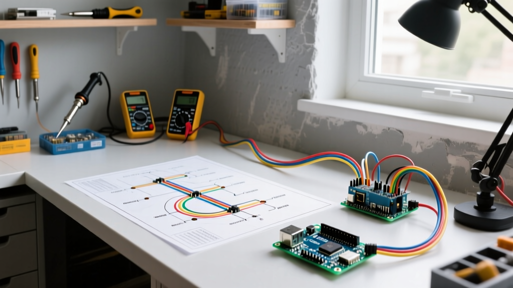
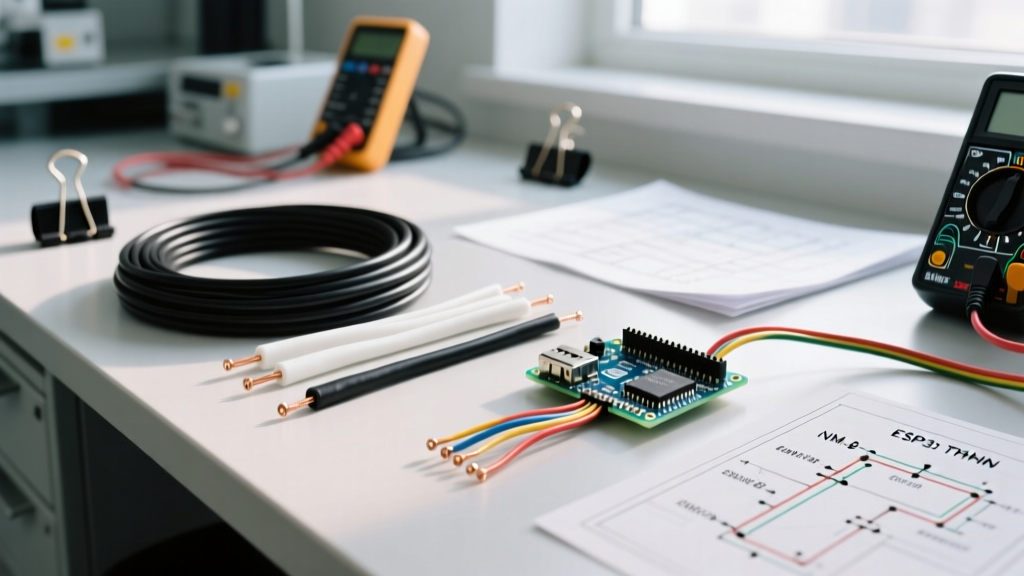
This comprehensive home project guide moves beyond basic outlet testers. We will cover advanced diagnostic techniques using digital multimeters (DMMs), non-contact voltage testers (NCVTs), and load-testing methods to identify hidden failure modes like loose neutrals, bootleg grounds, and degraded switch contacts.
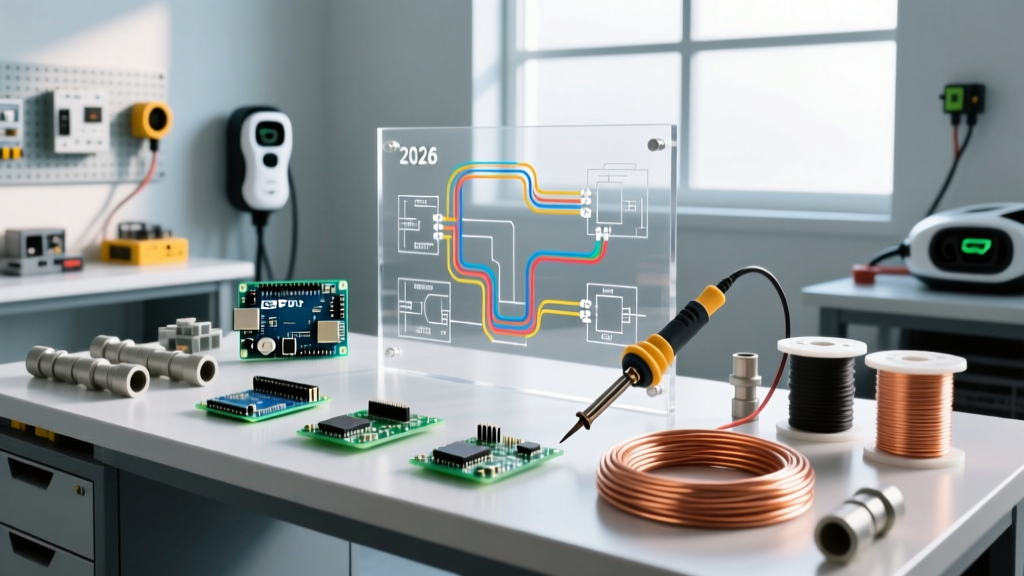
Essential Diagnostic Tools for 2026 Home Projects
Before opening a single junction box, you need the right instrumentation. Cheap, unrated meters are a liability when working near 120V/240V branch circuits.
- Non-Contact Voltage Tester (NCVT): The Klein Tools NCVT-2 (approx. $35) is a dual-range sensor that detects both standard 120V/240V and low-voltage 12V-48V doorbell or thermostat wiring, preventing false negatives.
- Digital Multimeter (DMM): For branch circuit testing, a True-RMS meter rated at CAT III 600V minimum is mandatory. The Fluke 117 (approx. $210) offers VoltAlert technology, while the budget-friendly Klein Tools MM400 (approx. $50) provides reliable CAT III protection for occasional DIY use.
- Receptacle Tester: The Gardner Bender GRT-3500 (approx. $15) provides instant visual fault codes for standard 15A and 20A 120V outlets.
Safety Directive: Never rely solely on an NCVT to confirm a circuit is de-energized before touching bare conductors. NCVTs can fail to detect voltage through thick wire insulation or in the presence of phantom voltage. Always verify with a contact multimeter.
Phase 1: Non-Contact and Receptacle Diagnostics
When approaching an existing circuit, start with non-invasive testing. Sweep the NCVT over the faceplate, switches, and junction box covers. If the NCVT remains silent, proceed to the receptacle tester.
Decoding Receptacle Tester LED Patterns
Plug-in testers are excellent for catching common wiring errors in older homes or rushed remodels. Below is the standard diagnostic matrix for a 3-light tester (Yellow-Yellow-Red configuration):
| Light Pattern (L to R) | Condition | Action Required |
|---|---|---|
| Off - Yellow - Yellow | Correct Wiring | No action needed. |
| Yellow - Off - Yellow | Open Ground | Verify ground wire connection at the receptacle and panel. Common in pre-1960s knob-and-tube retrofits. |
| Off - Off - Yellow | Open Neutral | Hazard: Loose neutral wire. Check wire nuts and backstabbed connections immediately. |
| Off - Yellow - Off | Open Hot | Circuit is dead or hot wire is disconnected. Verify breaker status. |
| Yellow - Yellow - Off | Hot/Ground Reversed | Severe Hazard: The grounding system is energized. Shut off breaker and rewire. |
| Yellow - Off - Red | Hot/Neutral Reversed | Polarity is reversed. Swap brass (hot) and silver (neutral) terminal wires. |
Phase 2: Precision Multimeter Voltage Testing
A receptacle tester only tells you if the wires are in the right holes; it does not tell you the quality of the connection. To test electrical wiring for voltage drop and hidden resistance, you must use a multimeter set to AC Voltage (V~).
The 3-Point Voltage Test
With the circuit energized, insert your multimeter probes into the receptacle slots and record the following three measurements:
- Hot to Neutral (Short slot to Long slot): Should read between 118V and 122V. If it reads below 115V, you have excessive voltage drop, indicating undersized wire for the run length or a loose connection upstream.
- Hot to Ground (Short slot to Ground hole): Should read identical to Hot-Neutral (118V-122V). If this reads 0V, your ground path is broken or you have a 'bootleg ground' (a jumper wire illegally connecting the neutral and ground terminals).
- Neutral to Ground (Long slot to Ground hole): Should read less than 2V (ideally 0.0V to 0.5V). If this reads higher than 2V, your circuit is heavily loaded, or worse, you have a loose neutral connection at the main service panel. The Consumer Product Safety Commission (CPSC) warns that loose neutrals cause severe arcing and are a primary catalyst for electrical fires.
Phase 3: Continuity Testing and Switch Diagnostics
Continuity testing verifies if an uninterrupted electrical path exists. CRITICAL RULE: You must shut off the circuit breaker and verify zero voltage before performing any continuity tests. Sending 120V into a multimeter set to the Ohms (Ω) or continuity setting will instantly blow the meter's internal fuse or destroy the logic board.
Testing a Standard Single-Pole Switch
Remove the switch from the box. Set your DMM to the continuity setting (the diode/soundwave icon). Touch one probe to the brass grounding screw and the other to the hot terminal screws. It should read 'OL' (Open Loop) or infinite resistance. If it beeps, the switch is internally shorted and must be replaced.
Decoding 3-Way Switch Continuity
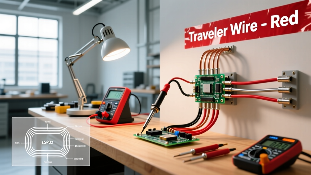
3-way switches are a frequent source of DIY frustration. They feature one 'Common' terminal (usually a black or dark-colored screw) and two 'Traveler' terminals (brass screws).
- Position 1: Place one probe on the Common screw and the other on Traveler 1. The meter should beep (continuity). Move the probe to Traveler 2; it should read OL (no continuity).
- Position 2: Flip the switch toggle. Probe Common to Traveler 1 (should read OL). Probe Common to Traveler 2 (should beep).
- Failure Mode: If both travelers show continuity to the common terminal simultaneously, the internal contacts are welded together. Replace the switch.
Advanced Troubleshooting: Load Testing for Hidden Faults
A circuit might show a perfect 121V with no load, but fail completely when a microwave or space heater is turned on. This indicates a high-resistance fault, often caused by 'backstabbed' (push-in) receptacle connections that have degraded over decades of thermal expansion and contraction.
To perform a load test:
- Plug a high-draw appliance (like a 1500W space heater) into the receptacle and turn it on.
- Immediately measure the Hot-to-Neutral voltage again.
- If the voltage drops by more than 5% (below ~114V), you have a high-resistance fault upstream.
- Turn off the power, remove the receptacle, and inspect the backstabbed wires. Cut off the stripped ends, re-strip the wire, and secure it under the side terminal screws using a torque screwdriver set to the manufacturer's specification (typically 14 in-lbs for standard 15A devices).
Dealing with Modern AFCI and GFCI Nuisance Tripping
In modern 2026 electrical codes, AFCI (Arc-Fault Circuit Interrupter) breakers are required in almost all living spaces. If your wiring tests perfectly for voltage and continuity, but the AFCI breaker trips randomly, you are likely dealing with a shared neutral (Multi-Wire Branch Circuit) miswired at the panel, or a degraded wire insulation causing micro-arcing. According to safety guidelines published by Fluke's electrical testing division, diagnosing AFCI trips requires checking for crossed neutrals between adjacent circuits using a clamp meter at the panel to ensure the neutral current perfectly matches the hot current on that specific breaker pole.
Summary Checklist for Safe Wiring Verification
- Always use a CAT III rated digital multimeter for branch circuits.
- Perform the 3-point voltage test (Hot-Neutral, Hot-Ground, Neutral-Ground) to catch bootleg grounds and loose neutrals.
- Never test continuity on a live circuit.
- Replace all backstabbed connections with side-wired or screw-terminal connections during remodels.
- Verify AFCI/GFCI functionality using the built-in test buttons, not just a plug-in tester, as plug-in testers cannot always simulate the exact micro-arc signatures required to trip modern AFCI breakers.