
The Blueprint: Planning Your E-Bike Wiring Harness
The renaissance of custom electric bicycle builds in 2026 has shifted from basic hub-motor kits to highly integrated, high-torque mid-drive retrofits. Whether you are breathing new life into a vintage 1980s steel Schwinn frame or fabricating a modern cargo hauler, the nervous system of your build relies on flawless electric bike throttle wiring. A poorly planned harness doesn't just lead to messy aesthetics; it introduces critical failure modes ranging from signal degradation to catastrophic controller runaway.
When planning a custom retrofit, the throttle circuit is a low-voltage, high-sensitivity pathway. Unlike the main phase wires carrying 40 to 100 amps from your battery to the motor controller, the throttle wiring operates on a delicate 5V logic system. This guide breaks down the exact architecture, connector ecosystems, and routing strategies required to design a reliable, waterproof, and safe throttle harness for your next e-bike renovation project.
Throttle Architecture: Analog Hall Effect vs. Digital CAN Bus
Before cutting a single wire, you must identify the communication protocol your chosen motor controller expects. In the aftermarket and retrofit space, two primary architectures dominate:
1. Linear Hall Effect (The Aftermarket Standard)
Over 90% of universal controllers (such as the Sabvoton SVMC72150 or generic 'KT' series controllers) rely on analog linear Hall effect sensors. As you twist the throttle grip, a magnet moves past the sensor, altering the magnetic field and outputting a variable voltage signal—typically ranging from 0.8V (idle) to 3.6V (wide-open throttle). This requires a simple 3-wire or 4-wire analog connection.
2. Digital CAN Bus / UART (OEM Integrated Systems)
If your renovation utilizes a proprietary mid-drive system like the Bafang M620 (Ultra) or a modern Bosch Smart System, the throttle does not output an analog voltage. Instead, it sends digital multiplexed packets over a CAN bus or UART line. Wiring a standard analog throttle to a CAN bus controller will result in immediate error codes (e.g., Error 08 on Bafang displays). Always verify your controller's pinout schematic before purchasing components.
Pinout Mapping and the 5V Logic Danger Zone
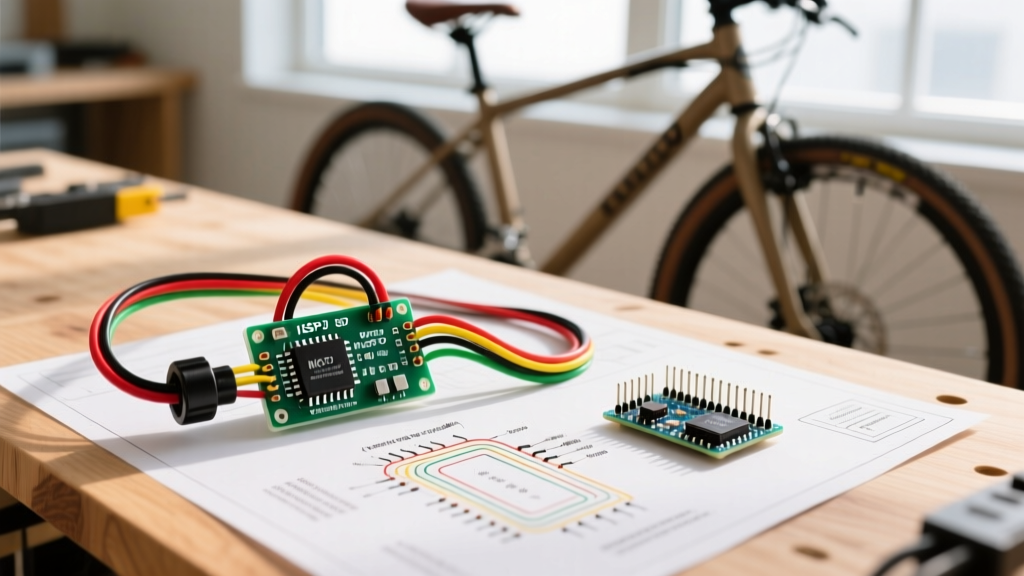
The most common fatal error in DIY electric bike throttle wiring is confusing the low-voltage logic lines with the high-voltage main power lines. Most universal throttles use a standard color code, but you must always verify with a multimeter.
| Wire Color (Standard) | Function | Voltage / Signal Type | Failure Consequence if Miswired |
|---|---|---|---|
| Red | VCC (Power) | 5V DC (Supplied by Controller) | Controller 5V regulator burns out; microcontroller destroyed. |
| Black | GND (Ground) | 0V (Logic Ground) | Throttle unresponsive; potential ground loop noise. |
| Green / White | Signal (PWM/Analog) | 0.8V to 3.6V Variable | Motor runaway (if shorted to 5V) or dead throttle. |
| Yellow (Optional) | Cruise Control / Lock | 5V Trigger | Unintended cruise engagement. |
Critical Safety Warning: Never splice the 5V Red VCC wire into your main 48V, 52V, or 72V battery line to 'get power'. The controller's internal buck converter must supply the 5V. Injecting main pack voltage into the 5V logic rail will instantly vaporize the controller's microprocessor and can weld the motor phase wires open, causing a dangerous crash.
Connector Ecosystem: Upgrading to IP67 Higo
Historically, DIY builders used SM-2.54 plastic connectors for throttle wiring. In 2026, these are considered obsolete for any external harness routing. SM connectors lack weatherproofing; moisture ingress creates a high-resistance bridge between the 5V VCC and the Signal wire, causing 'phantom throttle engagement' where the motor accelerates without rider input.
For any professional-grade retrofit, plan your harness around Higo (formerly Julet) IP67 waterproof connectors. Specifically, the Z910 series (3-pin and 4-pin) features gold-plated contacts and silicone O-ring seals that withstand high-pressure washing and submersion.
Harness Planning: Male vs. Female Orientation
A crucial planning step often overlooked is connector gender. To prevent short circuits if a cable is unplugged while the battery is live:
- Controller Side: Must use the FEMALE connector (pins are recessed inside the plastic housing).
- Throttle/Component Side: Must use the MALE connector (exposed pins).
This ensures that if the throttle is disconnected, the exposed pins on the throttle side carry no voltage, and the live 5V pins on the controller side are safely recessed and shielded from rain or accidental contact.
E-Brake Inhibitor Integration: The Mandatory Safety Loop
You cannot plan electric bike throttle wiring in isolation; it must be integrated with your e-brake motor inhibitors. When retrofitting vintage frames with mechanical disc brakes or hydraulic calipers, you must install brake levers with built-in microswitches or hydraulic pressure sensors.
The e-brake wiring runs in parallel to the throttle logic. When the brake lever is pulled, the switch grounds the controller's 'E-Brake' pin, instantly overriding the throttle signal and cutting power to the motor phase wires. For retrofits using Tektro or Magura hydraulic brakes, plan for the purchase of hydraulic brake sensors (approx. $25-$40 per pair) that splice directly into the Higo harness using a Y-splitter cable.
Step-by-Step Harness Routing for Frame Retrofits
Routing delicate 22 AWG signal wires through a bicycle frame requires protecting them from the high-voltage phase wires and the physical environment. Follow this routing protocol:
- Internal Down-Tube Routing: If running the battery discharge cable and throttle wires through the same down-tube, you must separate them. High amperage phase wires generate electromagnetic interference (EMI) that can induce noise in the analog throttle signal, causing erratic motor pulsing. Wrap the throttle wires in a copper-foil shielding tape and ground the shield to the controller chassis.
- Head-Tube Pivot Protection: The most common point of failure is where the wires cross the head-tube bearing. As the handlebars turn, wires can fray against the sharp steel edge of the frame. Install a rubber grommet or use a 3D-printed TPU head-tube cable guide to maintain a 5mm clearance from the metal edge.
- Drip Loops: Before the wire enters the controller enclosure, create a physical 'drip loop' (a U-shape pointing downward). This ensures that rainwater running down the cable jacket drips off the bottom of the loop rather than wicking directly into the controller's cable gland.
Workshop Tools and Budget Planning
Executing a custom harness requires specialized crimping tools. Soldering Higo connectors is highly discouraged, as the heat melts the internal nylon housing and destroys the IP67 seal. Budget for the following precision tools:
- Hozan P-707 Precision Crimper ($85 - $110): The industry standard for crimping Higo/Julet micro-pins without crushing the silicone seal ring.
- IWISS SN-28B ($25 - $35): Ideal for JST and standard SM-2.54 connectors if you are wiring internal display connections.
- 3M EPS200 Dual-Wall Heat Shrink ($15 per spool): Contains an inner layer of meltable adhesive that seals the wire entry point against moisture wicking.
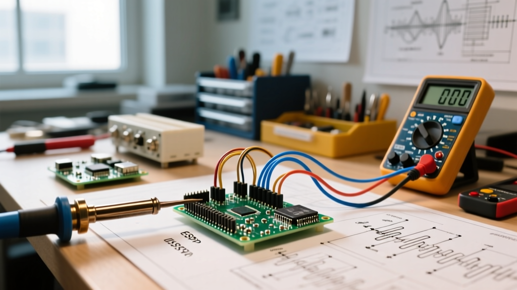
- Fluke 115 Multimeter ($250+): Essential for verifying the 0.8V to 3.6V signal sweep before connecting the motor.
For a comprehensive overview of safe e-bike assembly and mechanical integration, refer to expert guides like those published by Bicycling Magazine. Additionally, if your renovation project includes setting up a dedicated workshop charging station for high-capacity lithium packs, ensure your facility's electrical layout complies with local codes, referencing standards such as NFPA 70 (National Electrical Code) for proper circuit sizing and GFCI protection in damp garage environments.
Final Pre-Ride Diagnostic Checklist
Before your maiden voyage, elevate the rear wheel and perform a bench test. Turn the key, verify the display boots, and slowly twist the throttle. Use your multimeter to back-probe the signal wire at the controller connector. You should see a smooth, linear voltage climb from 0.8V to roughly 3.6V without any sudden spikes or dropouts. If the voltage jitters, you have a poor crimp or a damaged Hall sensor magnet. Only once the signal is verified smooth and the e-brake inhibitors successfully kill the motor should you put the bike on the pavement.