
The Evolution of Arduino Servo Wiring: From Prototype to Production
When transitioning a microcontroller project from a workbench prototype to a deployed robotic system, the weakest link is rarely the firmware—it is almost always the physical wiring. Specifically, Arduino servo wiring presents a unique set of electromechanical challenges. Servos are high-current, inductive loads that generate significant Electromagnetic Interference (EMI), draw massive stall currents, and are highly sensitive to voltage drops and PWM signal noise.
In 2026, the divide between hobbyist prototyping and professional electromechanical integration is stark. This analysis breaks down the DIY approach (breadboards and Dupont jumper wires) against professional wire harness assembly standards, providing actionable engineering data to help you design reliable actuator systems.
The DIY Paradigm: Dupont Wires and Breadboards
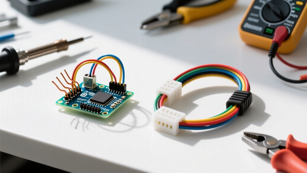
The standard DIY approach to Arduino servo wiring relies on 28 AWG Dupont jumper wires and solderless breadboards. While excellent for rapid prototyping, this method introduces severe electrical and mechanical liabilities when scaled.
Electrical Limitations and Voltage Drop
A standard 28 AWG copper wire has a resistance of approximately 0.0649 ohms per foot. However, the true bottleneck is the contact resistance at the Dupont terminal and the breadboard spring clips. A single breadboard connection can introduce 0.1 to 0.5 ohms of contact resistance. When driving a standard MG996R metal-gear servo, which can draw up to 2.5 Amps at stall (6V), this resistance causes a catastrophic voltage drop. The servo receives insufficient voltage, leading to erratic jitter, internal logic resets, and eventual motor burnout.
Pros and Cons of the DIY Jumper Method
- Pros: Zero tooling cost; immediate iteration; widely available in cheap kits ($5-$10).
- Cons: High contact resistance; zero vibration resistance; severe EMI susceptibility; maximum continuous current limited to ~1A per wire.
The Professional Standard: IPC/WHMA-A-620 Harnesses
Professional electrical engineering discards jumper wires in favor of custom wire harnesses built to IPC/WHMA-A-620 standards. This standard dictates the requirements and acceptance criteria for cable and wire harness assemblies, ensuring reliability in high-vibration, high-current environments.
Wire Selection and Crimping Architecture
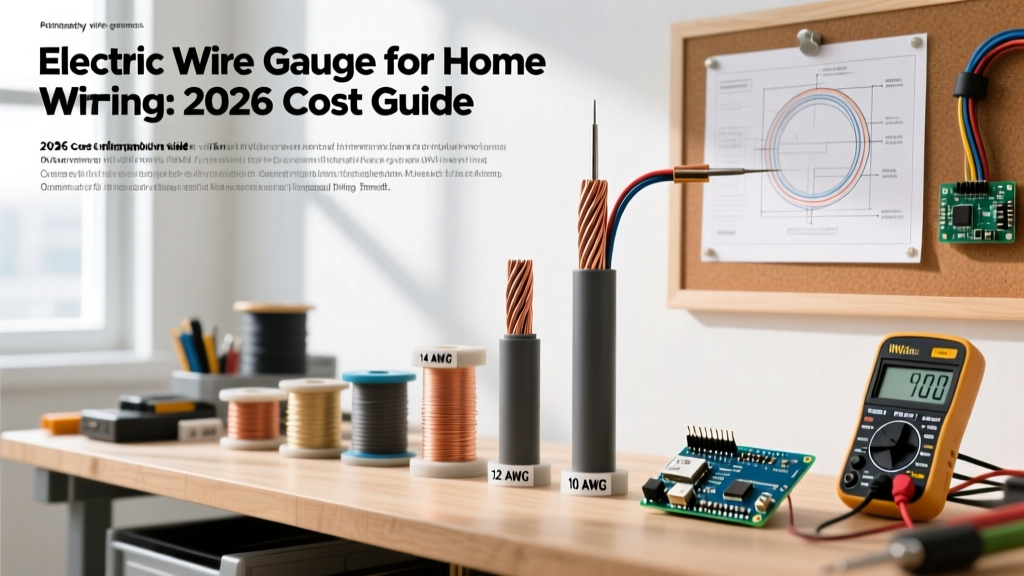
Professional Arduino servo wiring utilizes 22 AWG or 20 AWG stranded silicone wire. Silicone insulation withstands high temperatures and remains flexible, preventing work-hardening and copper strand breakage under continuous vibration. Connections are made using JST-XH (2.54mm pitch) or Molex Mini-Fit Jr. connectors, which feature positive locking mechanisms to prevent vibration-induced disconnects.
Crimping is performed with precision ratchet tools (like the Engineer PA-09 or IWISS SN-28B) to achieve a gas-tight connection. According to IPC-A-620 Class 2 and Class 3 standards, a proper crimp must exhibit no exposed copper strands outside the crimp barrel and must pass a strict pull-test without yielding.
Comparative Analysis: DIY vs. Professional Wiring Matrix
| Parameter | DIY Jumper Method | Professional Harness (IPC-A-620) |
|---|---|---|
| Wire Gauge | 28 AWG Stranded Copper | 22 AWG or 20 AWG Stranded Silicone |
| Connector Type | Friction-fit Dupont (0.1 inch) | Locking JST-XH or Molex Mini-Fit Jr. |
| Max Continuous Current | ~1.4 Amps | ~7.0 Amps (22 AWG) / ~11 Amps (20 AWG) |
| Contact Resistance | High (0.1Ω - 0.5Ω per node) | Negligible (<0.01Ω gas-tight crimp) |
| Vibration Resistance | Very Poor (backs out easily) | Excellent (positive locking latch) |
| Estimated Cost (per 3-wire servo lead) | $0.15 | $1.85 - $3.50 |
Power Architecture: Why the Arduino 5V Pin Fails
A critical failure point in amateur Arduino servo wiring is routing the servo power rail directly from the Arduino's 5V pin. As detailed in the Arduino Official Power Pin Documentation, the onboard linear voltage regulator (typically an NCP1117) can only safely dissipate enough heat to provide roughly 200mA to 500mA of continuous current, depending on the input voltage and ambient temperature.
Engineering Rule of Thumb: Never route inductive actuator power through a microcontroller's logic regulator. The back-EMF generated by a braking servo motor will induce voltage spikes that can permanently destroy the Arduino's ATmega328P or Renesas RA4M1 silicon.
The Professional Solution: UBECs and Isolated Rails
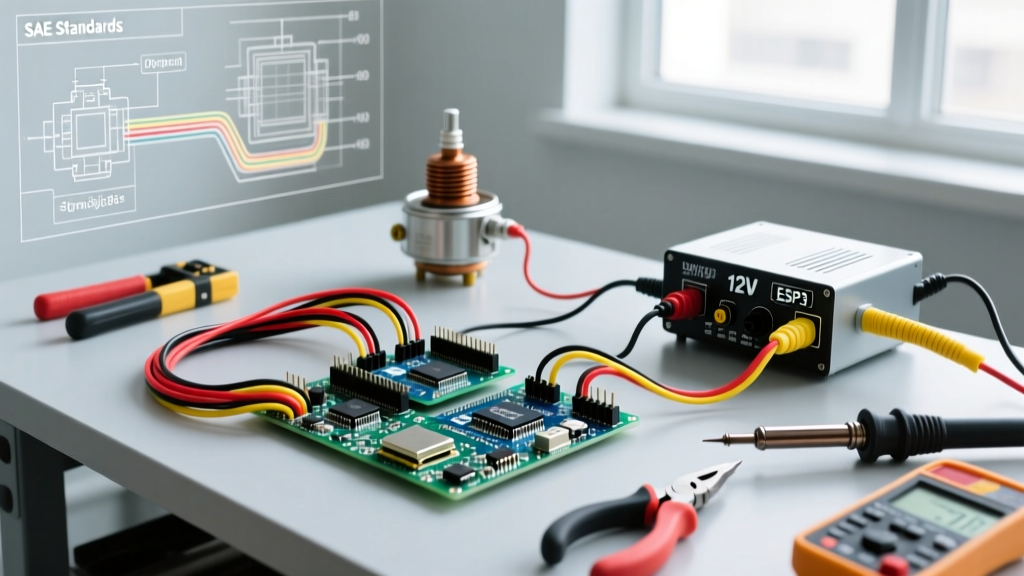
Professional systems utilize a UBEC (Universal Battery Elimination Circuit) or a high-efficiency switching buck converter. For a standard 4-servo robotic arm, a Hobbywing 5V/3A UBEC (retailing around $12 in 2026) or a Pololu Step-Down Voltage Regulator D24V50F5 is wired directly from the main LiPo battery to a dedicated terminal block. The Arduino and the servos share a common ground, but the high-current servo power completely bypasses the microcontroller's fragile PCB traces.
Signal Integrity: Mitigating PWM Noise and EMI
Servos operate on a 50Hz Pulse Width Modulation (PWM) signal, where the pulse width (typically 1000µs to 2000µs) dictates the angular position. Because the Pololu RC Servo User's Guide notes that servos have high-impedance control inputs, the PWM signal wire acts as an antenna, picking up EMI from the servo's own brushed DC motor.
Step-by-Step EMI Mitigation Strategy
- Twisted Pair Routing: Always twist the PWM signal wire tightly with its corresponding Ground wire (minimum 10 twists per inch). This ensures that any induced magnetic noise affects both wires equally, canceling out the interference at the receiver.
- Separate Power and Signal Bundles: Never run the high-current 20 AWG servo power wires in the same harness sleeve as the 22 AWG PWM signal wires. Keep them separated by at least 1 inch, or cross them at strict 90-degree angles.
- Logic Level Shifting: If running long cable runs (over 12 inches), the 5V logic from an Arduino Uno may degrade. Professionals use a 74HCT125 or SN74LVC8T245 buffer IC at the microcontroller end to boost the signal drive strength, ensuring sharp PWM edges.
Tooling and Cost Breakdown for Professional Harnesses (2026)
Transitioning to professional Arduino servo wiring requires an upfront investment in precision tooling. Here is the essential kit required to produce IPC-compliant harnesses:
- Engineer PA-09 Ratchet Crimper: ~$28. Essential for JST-XH and Dupont terminals; ensures uniform crimp pressure.
- IWISS SN-28B Crimping Tool: ~$22. An excellent alternative for smaller AWG pins.
- Wire Stripper (Fujiya AP-250): ~$35. Prevents nicking of fine stranded silicone wire.
- JST-XH 2.54mm Connector Kit (Pre-assembled housings & pins): ~$14 for 200 sets.
- 22 AWG Stranded Silicone Wire (4 Colors, 100ft spools): ~$45 total.
While the initial tooling cost hovers around $120 to $145, the per-unit cost of a custom 3-wire servo harness drops to under $2.00, yielding a product that will survive years of industrial or robotic operation without a single point of failure.
Final Verdict: When to Upgrade Your Wiring
If your project is a stationary, low-torque pan-and-tilt camera mount running for 10 minutes a day, DIY Dupont wiring is perfectly adequate. However, if your Arduino servo wiring involves high-torque metal-gear servos (like the DS3218 20kg servo), mobile robotics, continuous vibration, or commercial deployment, the DIY method is a liability. Upgrading to 22 AWG silicone wire, locking JST connectors, and isolated UBEC power rails is not just an aesthetic upgrade—it is a fundamental requirement for electromechanical reliability.