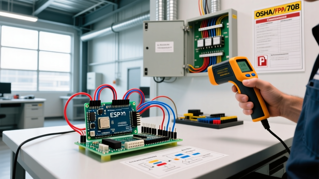

Redefining the Electrical Wiring Program for Modern Facilities
In commercial and industrial environments, an electrical wiring program is not merely a software application for drafting schematics; it is a comprehensive, facility-wide compliance and maintenance framework. For facility managers and electrical engineers, transitioning from a reactive 'run-to-failure' mindset to a programmatic, predictive approach is critical for mitigating arc flash hazards, preventing unplanned downtime, and satisfying stringent regulatory audits. A robust wiring program integrates baseline system mapping, predictive diagnostic testing, and digital work-order tracking to ensure every foot of conduit and every termination point meets current safety standards.
Historically, wiring inspections were treated as isolated, annual compliance checkboxes. Today, a mature electrical wiring program functions as a continuous lifecycle management system. It dictates the exact intervals for infrared thermography, insulation resistance testing, and torque verification, while leveraging Computerized Maintenance Management Systems (CMMS) to track asset degradation over time. This guide details the precise steps, equipment, and regulatory frameworks required to build an OSHA-compliant facility electrical wiring program from the ground up.
Regulatory Drivers: NFPA 70B and OSHA Mandates
The foundation of any compliant wiring program rests on two primary regulatory pillars. First, OSHA 29 CFR 1910.303 mandates that all electrical equipment and wiring be installed and maintained in a manner that ensures a safe working environment. OSHA inspectors frequently cite facilities under the 'General Duty Clause' if they cannot produce documented, scheduled maintenance records for their electrical distribution systems.
Second, the landscape shifted dramatically with the release of the 2023 edition of NFPA 70B (Standard for Electrical Equipment Maintenance). Previously a 'Recommended Practice,' NFPA 70B was elevated to a mandatory 'Standard.' This means that facilities are now legally and ethically bound to follow its prescribed maintenance intervals and testing protocols. Under NFPA 70B, an electrical wiring program must condition-based maintenance routines tailored to the specific environmental and operational stresses placed on the facility's wiring infrastructure.
Expert Insight: 'The elevation of NFPA 70B to a standard means that 'we've always done it this way' is no longer a valid defense during an OSHA audit or an insurance subrogation investigation following an electrical fire. Documentation of a structured wiring program is now your primary shield against liability.'
Step 1: Baseline Auditing and One-Line Diagram Verification
You cannot maintain what you have not mapped. The first phase of your electrical wiring program requires a comprehensive baseline audit. This involves verifying the facility's Single-Line Diagrams (SLDs) against the physical as-built conditions. Over decades of remodels and tenant improvements, branch circuits are often re-routed, and panel schedules become wildly inaccurate.
Arc Flash and Coordination Studies
Once the SLD is verified, the data must be imported into power systems analysis software like SKM Power*Tools for Windows (PTW) or ETAP. These programs model the wiring impedances, transformer sizes, and utility fault contributions to calculate incident energy levels (cal/cm²) at every bus and panel. For a mid-sized manufacturing facility (approx. 100,000 sq. ft.), a professional arc flash and coordination study typically costs between $12,000 and $18,000. This study dictates the required PPE categories and establishes the precise trip settings for adjustable circuit breakers, ensuring that downstream wiring is protected before thermal damage occurs.
Step 2: Implementing Predictive Thermography and Torque Audits
Loose electrical connections are the leading cause of commercial wiring failures. As conductors undergo thermal cycling (heating under load and cooling at night), mechanical lugs can loosen, increasing contact resistance. This resistance generates localized heat, which further degrades the connection in a runaway thermal loop.
Infrared (IR) Thermography Thresholds
Your wiring program must mandate annual or bi-annual IR scanning of all panelboards, switchgear, and motor control centers (MCCs) under at least 40% of normal load. According to the NETA Maintenance Testing Specifications (MTS), temperature differentials (Delta T) between identical components under similar loads dictate the urgency of remediation. Facilities should utilize high-resolution thermal imagers, such as the Fluke Ti480 PRO (approx. $6,500), to capture these anomalies.
| Delta T (°C) vs. Ambient | Condition Status | Programmatic Action Required |
|---|---|---|
| 1°C - 3°C | Possible Deficiency | Monitor; investigate during next scheduled outage. |
| 4°C - 15°C | Probable Deficiency | Schedule repair and re-torquing within 30 days. |
| > 15°C | Major Discrepancy | Immediate shutdown and repair required to prevent fire. |
Calibrated Torque Verification
Thermography must be paired with mechanical torque verification. NEC 110.14(D) strictly requires that terminations be tightened to the manufacturer's specified torque values using calibrated tools. For example, a 1/2-inch steel bolt securing a 250 kcmil aluminum conductor to a busbar typically requires exactly 450 in-lbs of torque. Your wiring program must include a digital torque wrench log, signed by the technician, uploaded to the facility's CMMS after every panel maintenance cycle.
Step 3: Insulation Resistance and Harmonic Mitigation
While thermography catches connection issues, it cannot see inside the conduit. Insulation degradation due to moisture, chemical exposure, or chronic overloading requires active testing.
Megger Testing Protocols
For standard 600V-rated THHN/THWN-2 conductors, your program should mandate insulation resistance testing using a megohmmeter (such as the Megger MIT485/2, approx. $1,200). Apply 1000V DC for one minute. While the absolute minimum acceptable resistance is often cited as 1 megohm per kilovolt plus 1, NETA MTS recommends a minimum of 100 megohms for new or healthy field-aged wiring. Any feeder reading below 50 megohms should be flagged for replacement or localized re-insulation.
Managing Harmonics in Modern Wiring
Modern facilities heavily utilize Variable Frequency Drives (VFDs) and switch-mode power supplies for LED high-bay lighting. These non-linear loads generate 3rd, 5th, and 7th harmonics. A standard True-RMS multimeter will miss the additive heat generated on the neutral conductor by triplen harmonics. Utilizing a Fluke 435 II Power Quality Analyzer (approx. $5,800) allows facility engineers to measure Total Harmonic Distortion (THD). If voltage THD exceeds 5% or current THD exceeds 20% on feeders, your wiring program must mandate the installation of K-rated transformers or active harmonic filters to prevent neutral conductor annealing and subsequent insulation failure.
Step 4: Digital Tracking via CMMS Integration
An electrical wiring program is only as effective as its tracking mechanism. Relying on spreadsheets guarantees that critical follow-ups will be missed. Integrating your testing data into a modern CMMS like Fiix or UpKeep (starting around $45 per user/month) creates a closed-loop compliance system.
- Asset Hierarchy: Build a parent-child hierarchy (e.g., Main Switchgear > Feeder Panel > Branch Circuit) so that recurring work orders are automatically generated based on the NFPA 70B frequency tables.
- Condition-Based Triggers: Configure the CMMS to automatically escalate a work order from 'Routine' to 'Urgent' if an attached IR scan image shows a Delta T exceeding 10°C.
- Historical Trending: Track the insulation resistance values of critical underground feeders year-over-year to predict dielectric failure before it causes a ground fault.
Cost Analysis: Budgeting Your Wiring Compliance Program
Establishing a comprehensive electrical wiring program requires upfront capital, but it drastically reduces the cost of emergency downtime, which averages $260,000 per hour for large manufacturing facilities. Below is a typical first-year budget for a 50,000 sq. ft. commercial facility.
| Program Component | Estimated First-Year Cost | Recurring Annual Cost |
|---|---|---|
| SLD Verification & Arc Flash Study | $8,000 - $12,000 | $0 (Update every 5 years) |
| IR Thermography (Outsourced NETA Tech) | $3,500 - $5,000 | $3,500 - $5,000 |
| Diagnostic Tools (Fluke Ti480, Megger) | $7,700 (Capital Expense) | $500 (Calibration) |
| CMMS Software Licensing (3 Users) | $1,620 | $1,620 |
| Remediation & Re-torquing Labor | Variable ($5,000+) | Variable |
Summary: Moving Beyond Reactive Maintenance
Building an OSHA-compliant facility electrical wiring program transforms your electrical infrastructure from a hidden liability into a managed, predictable asset. By anchoring your program in the mandatory requirements of NFPA 70B, utilizing predictive diagnostics like infrared thermography and harmonic analysis, and enforcing strict digital tracking via a CMMS, you ensure the safety of your personnel and the continuity of your operations. In an era where electrical systems are pushed closer to their thermal limits by modern non-linear loads, a structured, data-driven wiring program is no longer optional—it is a fundamental requirement of responsible facility management.