
The Anatomy of a Code-Compliant Light Bar Harness
Installing a high-output auxiliary LED light bar on a truck, Jeep, or marine vessel is not as simple as splicing into a headlight circuit. Modern 50-inch curved LED light bars from premium manufacturers like Rigid Industries or Baja Designs can draw between 20A and 35A at 12V. Direct switching through an OEM dashboard stalk or a standard toggle switch will melt the factory wiring and potentially cause an electrical fire. This is why understanding and executing a proper wiring harness diagram for light bar applications is critical.
From a code and standards perspective, a compliant harness isolates the high-current load from the low-current trigger circuit, utilizes automotive-grade wire insulation, and adheres to federal and industry safety regulations. In this guide, we dissect the engineering, code requirements, and component specifications necessary to build a harness that passes both technical scrutiny and legal compliance.
Core Circuit Topology: Reading the Diagram
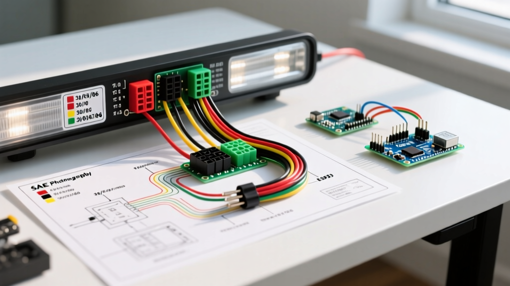
A standard, code-compliant wiring harness diagram for light bar setups relies on a heavy-duty relay to act as a remotely controlled switch. The topology is divided into two distinct circuits: the trigger circuit and the load circuit.
1. The Load Circuit (High Current)
- Power Source: 12V battery positive terminal.
- Overcurrent Protection: An ATO/ATC blade fuse or Mega fuse, sized at 125% of the light bar's maximum continuous draw (e.g., a 30A fuse for a 24A light bar), placed within 18 inches of the battery.
- Relay Terminal 30 (Input): Receives fused 12V power.
- Relay Terminal 87 (Output): Sends 12V power to the light bar's positive input.
- Ground: The light bar's negative wire routes directly to a clean, bare-metal chassis ground or back to the battery negative terminal.
2. The Trigger Circuit (Low Current)
- Switch Power: Taps into an ignition-switched or high-beam-switched 12V source.
- Relay Terminal 86 (Coil +): Receives the switched 12V signal.
- Relay Terminal 85 (Coil -): Grounds the relay coil to activate the electromagnet.
Navigating FMVSS 108 and DOT Auxiliary Lighting Codes
When wiring auxiliary lighting for on-road or mixed-use vehicles, you must comply with the Federal Motor Vehicle Safety Standards (FMVSS), specifically FMVSS 108, which governs lamps, reflective devices, and associated equipment. The National Highway Traffic Safety Administration (NHTSA) strictly regulates how auxiliary lights interact with factory lighting systems.
Code Requirement: Auxiliary driving lamps must not be wired to operate simultaneously with high beams if the combined candela output exceeds federal limits. Furthermore, a dedicated dashboard indicator light (typically blue) is legally required to inform the driver when the auxiliary light bar is energized.
To meet this in your wiring harness diagram, the trigger wire (Terminal 86) should be routed through a secondary dashboard toggle switch that is back-fed by the high-beam circuit via a diode or an isolated relay. This ensures the light bar can only be activated when the high beams are on, and the toggle switch acts as a master kill-switch, preventing accidental blinding of oncoming traffic.
SAE J1128 Wire Standards and Ampacity Matrix
Never use generic copper wire (like THHN building wire) for automotive light bar harnesses. The Society of Automotive Engineers (SAE) standard SAE J1128 dictates the requirements for low-tension primary cable used in surface vehicles. You must use GXL (thin-wall) or TXL (extra-thin-wall) wire, which features cross-linked polyethylene (XLPE) insulation rated for 125°C, offering superior resistance to engine bay heat, oil, and abrasion.
Below is the engineering matrix for selecting the correct SAE J1128 GXL wire gauge based on a standard 12V system, maintaining a maximum 3% voltage drop (0.36V) to ensure the light bar's internal PWM drivers do not trigger low-voltage shutoffs.
| Wire Gauge (AWG) | Max Continuous Ampacity | Max Run Length (12V / 3% Drop) | Typical Application |
|---|---|---|---|
| 14 AWG | 15 Amps | 12 Feet | Small 10-inch ditch lights, relay trigger circuits |
| 12 AWG | 20 Amps | 18 Feet | Standard 20-inch light bars, fog light pods |
| 10 AWG | 30 Amps | 24 Feet | 30-inch to 40-inch curved LED light bars |
| 8 AWG | 45 Amps | 30 Feet | 50-inch high-output light bars, multi-bar setups |
Component Selection: Relays, Fuses, and Connectors
A harness is only as reliable as its weakest termination point. Sourcing commercial-grade components is non-negotiable for a compliant build.
1. The Relay
Use a standard ISO mini 4-pin relay rated for at least 40A. The Hella 4RD 933 332-001 (approx. $7.50) is an industry benchmark, featuring a sealed coil and copper-alloy contacts that resist micro-welding under high inrush currents. Cheap, unbranded relays often use aluminum contacts that pit and fail within months.
2. Connectors and Terminations
Exposed spade terminals are a code violation in marine and off-road environments due to moisture ingress. All connections outside the cabin must utilize sealed connectors. The Deutsch DT series (IP68 rated) is the standard for auxiliary lighting. A 2-pin DT plug kit (approx. $12) requires a specific crimp tool (like the Delphi 12094250 or an IWISS IWS-3220M) to properly deform the wire crimp barrel without damaging the insulation crimp.
3. Marine Crossover Standards
If you are wiring a light bar on a center-console boat or a marine utility vehicle, the American Boat and Yacht Council (ABYC) standards supersede automotive norms. ABYC E-11 requires stranded, tinned marine-grade wire (UL 1426) to prevent black wire corrosion, and mandates that overcurrent protection be placed within 7 inches of the battery connection.
Edge Cases and Common Code Violations
Even experienced DIYers make critical errors when interpreting a wiring harness diagram for light bar projects. Avoid these common failure modes:
- The Backfeed Violation: Tapping the relay trigger (Terminal 86) directly into the factory high-beam wire without a diode or isolation relay. When the light bar is switched off, voltage can backfeed into the vehicle's CAN-bus system, triggering 'bulb out' dashboard warnings or frying the BCM (Body Control Module).
- Undersized Ground Paths: Routing the light bar's ground wire back to the battery is ideal, but if grounding to the chassis, the paint must be completely removed down to bare metal. A poor ground increases resistance, generating heat at the ring terminal and causing the light bar to flicker as the internal driver attempts to compensate for voltage fluctuations.
- Missing Dash Indicator: Failing to wire a secondary LED indicator light into the cabin. As noted in FMVSS 108, the driver must have a clear visual cue that the high-candela auxiliary lamps are active.
Step-by-Step Routing and Termination Protocol
- Disconnect Power: Remove the negative battery terminal before beginning any work.
- Mount the Relay: Secure the relay in a dry, ventilated area of the engine bay, preferably on the firewall or inner fender well, away from exhaust headers.
- Run the Load Wire: Route the 10 AWG or 8 AWG GXL wire from the battery to the relay, and from the relay to the front grille/bumper mount. Use split-loom tubing and Tesa tape to protect against abrasion.
- Crimp and Seal: Crimp the Deutsch DT pins onto the light bar's pigtail. Insert them into the housing until you hear the audible click, then insert the orange secondary locking wedge.
- Install the Fuse: Crimp the ATO fuse holder inline on the battery side of Terminal 30. Do not insert the fuse blade yet.
- Wire the Trigger: Run 14 AWG wire from the cabin switch, through a rubber firewall grommet, to Terminal 86. Ground Terminal 85 to a clean chassis point.
- Final Test: Reconnect the battery, insert the fuse, and test the system. Verify that the light bar only activates when both the dash toggle and the high beams are engaged.
Frequently Asked Questions
Can I use a standard 30A automotive fuse for a 28A light bar?
While a 30A fuse will technically hold, electrical codes and best practices dictate sizing the fuse at 125% of the continuous load to prevent nuisance blowing during the initial inrush current spike when the LED capacitors charge. For a 28A light bar, a 35A or 40A ATO/MAXI fuse paired with 8 AWG wire is the engineered solution.
Do I need a wiring harness if my light bar came with one?
Many budget light bars include generic, unbranded harnesses that utilize undersized 16 AWG CCA (Copper Clad Aluminum) wire and unsealed relays. These do not meet SAE J1128 standards and pose a severe fire risk. Always discard cheap included harnesses and build or purchase a heavy-duty, code-compliant harness using GXL wire and IP68 connectors.