
Why Parallel Wiring is the Standard for Home Receptacles
When expanding a room's electrical capacity or remodeling an older home, wiring electrical outlets in parallel is the only code-compliant and functional method for standard branch circuits. In a parallel configuration, the voltage remains constant across every receptacle on the circuit, while the current draw is additive. This ensures that plugging a 1,500W space heater into the last outlet on a 20-amp circuit delivers the exact same 120 volts as the first outlet nearest to the panel.
Unlike holiday light strings wired in series—where one burnt bulb kills the entire run—a parallel circuit ensures that if one receptacle fails or is removed, the downstream outlets continue to receive power. Understanding the physics and the National Electrical Code (NEC) requirements behind this setup is critical for any DIYer to prevent voltage drop, overheating, and electrical fires.
Series vs. Parallel: The Critical Difference
To grasp why the NEC mandates parallel wiring for receptacles, it helps to contrast it with series wiring. Below is a technical breakdown of how the two topologies behave in a residential 120V environment.
| Characteristic | Series Wiring (Not Code-Compliant) | Parallel Wiring (NEC Standard) |
|---|---|---|
| Voltage Delivery | Divides across loads (e.g., 60V per outlet on a 3-outlet run) | Constant 120V at every single receptacle |
| Current Flow | Same current flows through all devices | Current divides based on the specific load plugged into each outlet |
| Failure Mode | One loose wire or failed device breaks the entire circuit | Downstream devices remain powered even if an upstream receptacle is removed |
| Wire Sizing | Complex; requires calculating cumulative resistance | Standardized; 14 AWG for 15A, 12 AWG for 20A circuits |
NEC Code Requirements You Cannot Ignore
The National Fire Protection Association (NFPA) outlines strict rules in NFPA 70 (the NEC) regarding how parallel circuits must be spliced and maintained. The most critical concept for DIYers is the continuity of the equipment grounding conductor and the neutral wire.
The Danger of Relying on the Receptacle for Continuity
Historically, electricians would "daisy-chain" outlets by connecting the incoming hot and neutral wires to one set of terminal screws, and the outgoing wires to the other set. While this technically creates a parallel circuit, it violates the spirit of safe maintenance. If a homeowner removes that receptacle to paint the room or replace a broken faceplate, the downstream outlets lose their neutral path. According to the U.S. Consumer Product Safety Commission (CPSC), interrupted neutral paths can lead to erratic voltages and severe fire hazards, especially on multiwire branch circuits (MWBCs).
Pro-Tip: Always use "pigtailing" for your ground and neutral wires. This ensures the circuit's continuity relies on wire nuts or push-in connectors inside the junction box, not on the brass or silver screws of the receptacle itself.
Materials and Tools for a 20-Amp Branch Circuit
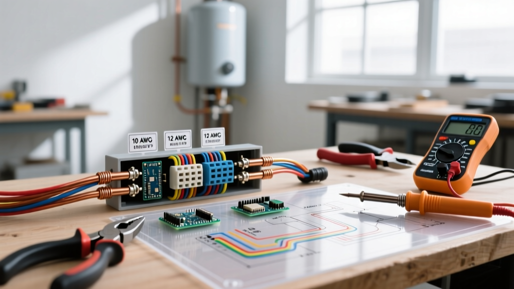
For modern homes, 20-amp circuits using 12 AWG wire are the standard for kitchen, bathroom, and general living area receptacles. Here is the exact bill of materials and estimated 2026 pricing for a professional-grade parallel installation.
| Item | Specific Model / Type | Est. Cost (2026) |
|---|---|---|
| Wire | Southwire 12/2 NM-B Romex (with ground) | $0.48 / linear ft |
| Receptacle | Leviton Decora 5262-W (20A, Tamper-Resistant) | $3.85 each |
| Splicing Connectors | WAGO 221 Series 412 (2-Port Lever-Nuts) | $0.38 each |
| Wire Strippers | Klein Tools 11063W (Katapult for 12 & 14 AWG) | $28.00 |
| Torque Screwdriver | Wiha 01460 (Set to 14 in-lbs for terminal screws) | $85.00 |
Step-by-Step: Wiring Electrical Outlets in Parallel Using Pigtails
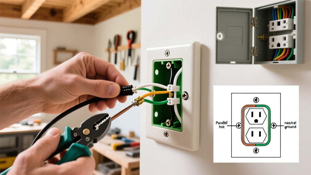
Pigtailing is the gold standard for wiring electrical outlets in parallel. It involves connecting the incoming line wires, the outgoing load wires, and a short "pigtail" wire together using a connector, then attaching the single pigtail to the receptacle.
- Prepare the Box: Ensure the electrical box has adequate fill capacity. A standard single-gang box (18 cubic inches) can comfortably hold one 20A receptacle, two 12/2 NM cables (incoming and outgoing), and three WAGO connectors.
- Strip the Wires: Using your Klein Tools strippers, remove exactly 3/4 inch of insulation from the black (hot), white (neutral), and bare (ground) wires. The WAGO 221 connectors have a built-in strip gauge on the side of the clear housing—use it to verify your length.
- Create the Pigtails: Cut three 6-inch lengths of spare 12 AWG THHN wire (black, white, and green/bare). Strip 3/4 inch off one end of each.
- Splice the Neutrals: Insert the incoming white wire, the outgoing white wire, and the white pigtail into a WAGO 221 connector. Flip the orange levers down to lock them. Give each wire a gentle tug test.
- Splice the Hots: Repeat the process with the black wires using a second WAGO connector.
- Splice the Grounds: Connect the bare copper wires using a third WAGO connector or a traditional green wire nut. (Note: WAGO connectors are now fully UL-listed for grounding applications and are preferred for their vibration resistance).
- Terminate at the Receptacle: Attach the white pigtail to a silver terminal screw and the black pigtail to a brass terminal screw. Always loop the wire clockwise around the screw so tightening pulls the loop closed.
- Torque to Spec: Use a torque screwdriver set to 14 in-lbs (check the manufacturer's stamp on the back of the Leviton receptacle) to tighten the terminal screws. This prevents thermal expansion and contraction from loosening the connection over time.
The "Pass-Through" Method: When is it Acceptable?
If you are only wiring a single, dead-end outlet at the end of a run, or if you are using the receptacle strictly as a pass-through for the hot wire only, you can use the device's terminal screws to hold two wires. However, you must adhere to these strict rules:
- Never put two wires under a single screw. Use the top screw for the incoming wire and the bottom screw for the outgoing wire.
- Break the brass fin tab ONLY if necessary. The brass tab connects the top and bottom hot terminals. Leave it intact for standard parallel wiring. Only break it if you are creating a split-wired receptacle (e.g., top half switched, bottom half always hot).
- Never use the "backstab" push-in holes for 12 AWG wire. While some 20A receptacles accept 12 AWG in the backstab holes, the internal spring-loaded clamps are notorious for loosening under heavy loads, leading to high-resistance arcing.
Common Failure Modes and Troubleshooting
Even when wiring electrical outlets in parallel correctly, specific environmental and mechanical factors can cause failures down the road.
1. High-Resistance Thermal Cycling
If terminal screws are not torqued to the manufacturer's specification, the copper wire will expand when a high-draw appliance (like a vacuum or hair dryer) is used, and contract when it cools. Over hundreds of cycles, the wire works itself loose. This creates a microscopic air gap that results in electrical arcing and melted plastic faceplates.
2. Shared Neutral Backfeed (MWBC Hazards)
If you are working in an older home with a Multiwire Branch Circuit (two hot legs sharing one neutral), you must never disconnect the neutral wire from the pigtail splice while the circuit is live. Doing so forces the 240V potential across the downstream 120V appliances, instantly destroying electronics and posing a lethal shock hazard. Always use a two-pole breaker or handle-ties for MWBCs as required by NEC Article 210.4.
3. Reversed Polarity
Connecting the black hot wire to the silver screw and the white neutral to the brass screw creates a reversed polarity condition. While the outlet will still power a lamp, the internal fuse of a plugged-in appliance will no longer protect the device correctly, and the outer metal shell of a screw-in lightbulb fixture will become energized, presenting a severe shock hazard.
Frequently Asked Questions
Can I wire a GFCI outlet in parallel with standard outlets?
Yes, but you must wire the downstream standard outlets to the "LOAD" terminals of the GFCI receptacle. If you wire them to the "LINE" terminals (using pigtails), the downstream outlets will be in parallel electrically, but they will not receive ground-fault protection from the GFCI.
How many outlets can I put on a single 20-amp parallel circuit?
The NEC does not specify a hard maximum number of receptacles on a residential 20-amp circuit. However, standard electrical engineering practice limits this to 10 to 13 receptacles to prevent nuisance tripping and excessive voltage drop, assuming a diverse load profile rather than all outlets drawing maximum current simultaneously.
Do I need to pigtail the ground wire if the box is metal?
Yes. If you are using a metal junction box, the equipment grounding conductor must be pigtailed to both the metal box (using a green grounding screw or clip) and the receptacle's green terminal screw. The receptacle cannot rely on the metal mounting yoke for a reliable ground path unless it is specifically listed as "self-grounding" and mounted firmly to a clean, unpainted metal box.