
The Renovation Imperative: Pre-Wiring for Smart Lighting
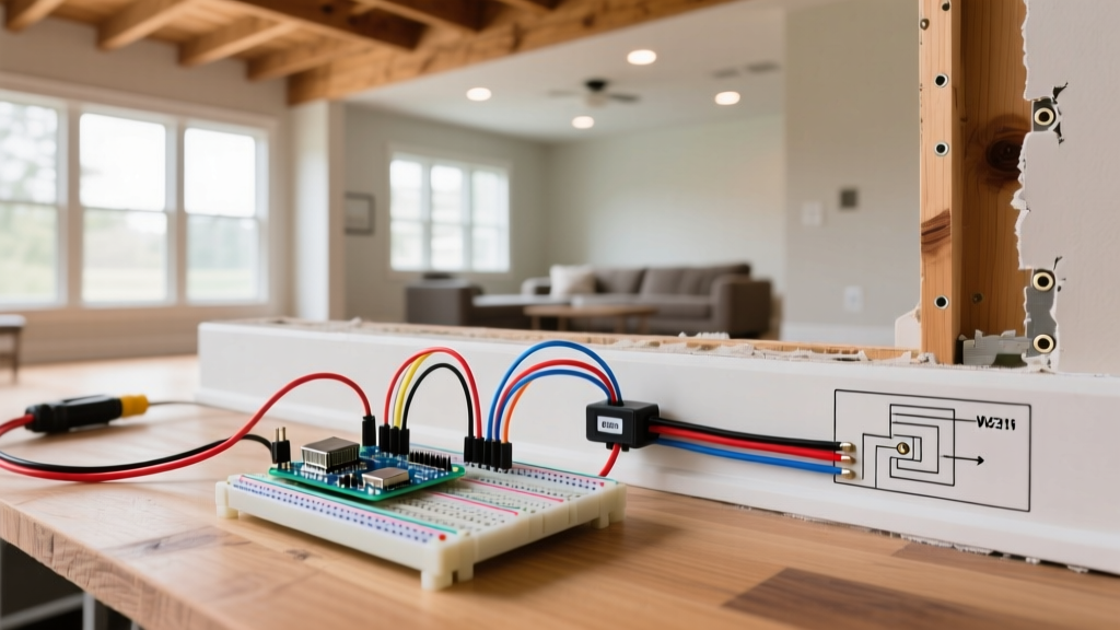
Integrating custom, programmable lighting into a home remodel elevates the space from standard to spectacular. However, executing a flawless LED wiring Arduino project requires rigorous pre-drywall planning. Unlike standard 120V AC circuits, low-voltage addressable LED systems are highly sensitive to voltage drop, data signal degradation, and thermal throttling. If you wait until the drywall is hung to figure out your microcontroller placement and power injection points, you are setting yourself up for flickering lights, dead pixels, and torn-open walls.
In 2026, the standard for high-end renovations involves embedding addressable LED strips into coffered ceilings, stair treads, and custom cabinetry, driven by Arduino-compatible microcontrollers integrated with Home Assistant via Wi-Fi. This guide details the exact architectural, electrical, and component-level strategies required to plan a permanent, code-compliant smart lighting infrastructure during your renovation.
Phase 1: Pre-Drywall Routing and NEC Compliance
Before the framing inspection, you must establish the physical pathways for your low-voltage wiring. While low-voltage lighting is generally exempt from the strict conduit requirements of 120V mains, it must still adhere to safety standards to prevent fire hazards and interference.
NEC Article 725 and Class 2 Circuits
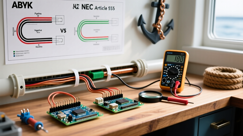
Addressable LED strips powered by external, UL-listed power supplies typically fall under Class 2 circuit classifications. According to NFPA 70 (National Electrical Code), Class 2 wiring must be separated from 120V AC mains to prevent inductive interference and accidental cross-contact.
- Physical Separation: Maintain at least a 2-inch gap between your low-voltage LED data/power lines and standard Romex (NM-B) AC wiring inside wall cavities.
- ENT (Smurf Tube): Run 1/2-inch or 3/4-inch Electrical Nonmetallic Tubing (ENT) from your central structured media panel to every lighting zone. This allows you to pull new data or power cables years later without destroying your drywall.
- Plenum Ratings: If your wiring passes through HVAC return air spaces (like a dropped ceiling acting as a plenum), you must use CL2P or CL3P rated cables to prevent toxic smoke circulation in the event of a short.
Phase 2: Component Selection for Permanent Installs
Prototyping on a breadboard with an Arduino Uno and cheap WS2812B strips is fine for a desk toy. For a permanent home renovation, you need industrial-grade reliability. The table below outlines the exact components you should specify in your renovation budget.
| Component Category | Hobbyist Choice (Avoid) | Renovation-Grade Choice (Specify) | Estimated Cost (2026) | Why It Matters for Remodels |
|---|---|---|---|---|
| Microcontroller | Arduino Uno R3 | ESP32-DevKitC V4 (Arduino IDE) | $6.50 - $9.00 | Built-in Wi-Fi for Home Assistant/Matter integration; compact enough to hide in junction boxes. |
| LED Strip | WS2812B (5V) | WS2815 (12V Addressable) | $28.00 - $35.00 / 5m | 12V reduces voltage drop over long runs; features a backup data line so one dead pixel won't kill the whole strip. |
| Power Supply | Generic Brick PSU | Mean Well LRS-150-12 (150W) | $32.00 - $38.00 | UL-listed, enclosed metal chassis, built-in thermal overload protection, and a 3-year warranty. |
| Data Wiring | 28 AWG Jumper Wires | 18 AWG Shielded 4-Core Cable | $0.85 / ft | Shielding prevents data corruption from nearby AC mains; 18 AWG handles power injection efficiently. |
Phase 3: The Wiring Architecture and Power Injection
The most common failure mode in DIY smart home renovations is severe voltage drop, resulting in the LEDs at the end of a run turning pink or flickering. The WS2815 strip draws approximately 18mA per pixel at 12V. A standard 5-meter reel with 60 LEDs per meter will pull up to 5.4 Amps at full white.
Calculating Power Injection Points
You cannot power a 5-meter run from a single end. During the rough-in phase, you must plan power injection points every 2.5 meters.
Renovation Pro-Tip: Run a dedicated 14 AWG or 12 AWG power trunk line from your Mean Well power supply to the far end of the lighting zone. From this trunk, use 18 AWG pigtails to inject 12V and Ground into the strip every 2.5 meters. Do not inject 5V data into these mid-run points—only power and ground.
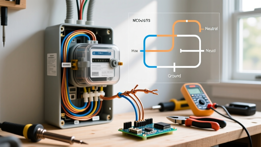
Always connect the grounds of your power supply, your ESP32 microcontroller, and every LED strip segment together. A missing common ground is the primary cause of erratic data signals and blown microcontroller pins.
Phase 4: Data Line Integrity and Logic Level Shifting
When mapping out your LED wiring Arduino architecture, data signal degradation over distance is a critical edge case. The WS2815 protocol requires a crisp 5V logic signal. However, modern Arduino-compatible boards like the ESP32 output 3.3V logic. While a short 10cm jumper wire might work on a desk, running 3.3V logic through 15 feet of in-wall cabling will result in capacitive coupling and data loss.
The SN74AHCT125 Solution
To guarantee signal integrity inside walls, you must install a logic level shifter at the microcontroller origin. The SN74AHCT125 chip is the industry standard for this application. It safely translates the ESP32's 3.3V data output into a robust 5V signal powered directly from the Mean Well PSU.
- Resistor Placement: Solder a 470-ohm resistor directly to the data-in pad of the first LED strip. This protects the first pixel's logic gate from inductive spikes.
- Capacitor Buffering: Install a 1000µF, 25V electrolytic capacitor across the VCC and Ground terminals at the power supply output to absorb initial current surges when the LEDs turn on.
For comprehensive wiring schematics and safety protocols regarding addressable strips, the Adafruit NeoPixel UberGuide remains the definitive engineering reference for logic translation and power management.
Phase 5: Thermal Management and Aluminum Extrusions
Addressable LEDs generate significant heat, especially when driven at high brightness in warm white or full RGB modes. Peeling the adhesive backing off a WS2815 strip and sticking it directly to raw drywall or the inside of a wooden cabinet is a guaranteed way to degrade the LEDs and cause premature adhesive failure.
Specifying the Right Channels
During the finishing phase of your renovation, you must install aluminum LED channels. Aluminum acts as a passive heat sink, pulling thermal energy away from the PCB.
- Surface Mount Channels: Use 17mm wide aluminum U-channels with frosted polycarbonate diffusers for under-cabinet kitchen lighting. This eliminates the 'spotting' effect of individual LEDs on granite or quartz countertops.
- Recessed Drywall Channels: For coffered ceilings or stair nosing, specify flanged aluminum profiles. These allow the drywaller to mud and tape directly over the aluminum flanges, creating a seamless, invisible light source.
- IP Ratings: For bathroom vanities or outdoor eave renovations, specify IP67 (silicone tube encased) strips. However, be aware that the silicone traps heat, requiring you to reduce the maximum software brightness limit to 70% to prevent thermal throttling.
Coordinating with Your Contractor
A successful LED wiring Arduino renovation requires strict coordination between the low-voltage integrator, the electrician, and the cabinet maker. Ensure your cabinet maker provides exact millimeter measurements of recessed grooves before you order your aluminum extrusions. Ensure your electrician installs a dedicated 15A 120V AC circuit with a physical switch that feeds *only* the Mean Well power supplies, allowing you to hard-cut power to the lighting system without affecting other room outlets.
By treating your low-voltage smart lighting with the same rigorous planning as your high-voltage mains, you will create a permanent, maintenance-free architectural lighting system that seamlessly integrates with the modern smart home ecosystem.