
The Shift from Hobbyist to Industrial: Why Compliance Matters
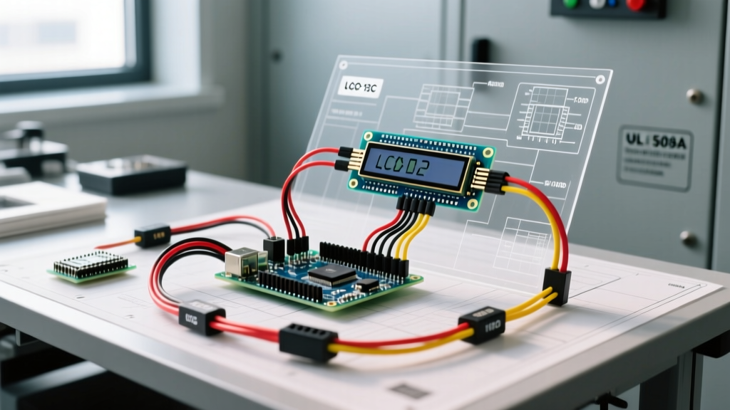
When engineers transition from prototyping on a workbench to deploying custom environmental monitors or automated manufacturing jigs, the rules of engagement change entirely. A standard lcd screen arduino wiring setup using jumper wires and a breadboard is perfectly acceptable for a university lab. However, when that same Arduino Mega 2560 Rev3 and 20x4 I2C LCD display are mounted inside a NEMA 4X enclosure to control commercial HVAC dampers or monitor server room ambient conditions, the wiring must pass rigorous municipal and industrial inspections.
In 2026, electrical inspectors and third-party testing agencies are increasingly scrutinizing low-voltage control panels that utilize commercial off-the-shelf (COTS) microcontrollers. The primary frameworks governing these installations are NFPA 70 (National Electrical Code) Article 725 for Class 2 and Class 3 circuits, and UL 508A for Industrial Control Panels. Failing to adhere to these standards can result in rejected inspections, voided insurance policies, and catastrophic field failures.
NEC Article 725 and Power Supply Isolation
The most common point of failure during an inspection of an Arduino-based control panel is the power supply. Microcontrollers and LCD screens typically operate at 5V DC or 3.3V DC. Under NEC Article 725, if your circuit is classified as a Class 2 circuit (which limits power to 100VA and prevents fire initiation), the power supply must be inherently limited and UL 1310 listed.
Using a generic, unbranded 5V switching power supply sourced from online marketplaces (often costing around $8 to $12) will immediately flag a red sticker from an inspector. Commercial panels require DIN-rail mounted, UL-listed power supplies. For example, the Mean Well HDR-15-5 (typically priced between $35 and $45) is a UL 1310 Class 2 compliant power supply specifically designed for control panel integration. It provides the clean, isolated 5V DC required by both the Arduino and the LCD backlight without risking high-voltage crossover.
Wiring Specifications for I2C LCD Interfaces
Most modern Arduino LCD setups utilize a PCF8574T I2C backpack to reduce the wiring footprint from 12+ pins down to just four (VCC, GND, SDA, SCL). However, I2C is notoriously susceptible to electromagnetic interference (EMI) and capacitance issues in industrial environments.
| Parameter | Hobbyist Standard | Industrial Compliance Standard |
|---|---|---|
| Wire Type | Unshielded Dupont Jumpers | Belden 8723 Shielded Twisted Pair |
| Wire Gauge | 28 AWG (Stranded) | 22 AWG (Stranded) with Ferrules |
| Max Bus Capacitance | Not Verified | 400pF (Per NXP I2C Specification) |
| Max Cable Length | Variable (Often >1m) | <30cm (Without PCA9600 Bus Extender) |
| Termination | Solder or Pin Header | DIN-Rail Terminal Blocks (e.g., Phoenix Contact) |
Step-by-Step Inspection Checklist for LCD Arduino Circuits
When preparing a custom Arduino control panel for final inspection, use this rigorous checklist to ensure your lcd screen arduino wiring meets commercial standards.
- Verify Power Supply Listings: Check that the 5V power supply has a visible UL or CSA mark and is rated for Class 2. Ensure the 120V AC input side is wired with proper 18 AWG or 16 AWG machine tool wire (MTW) and protected by a correctly sized branch circuit breaker.
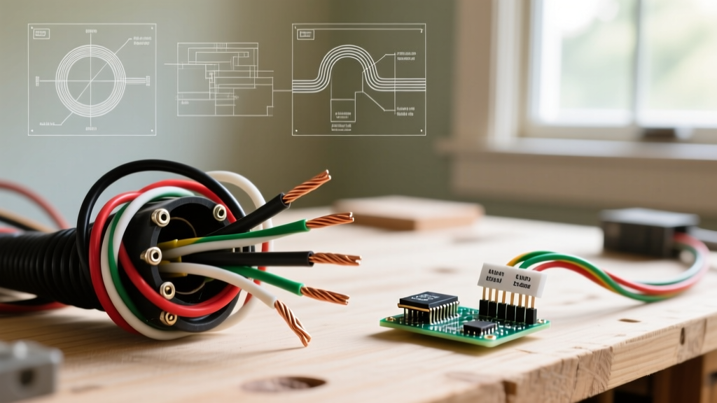
- Inspect Termination Methods: Inspectors will reject panels where stranded wires are simply twisted and stuffed into screw terminals. All stranded wires entering the Arduino screw shield or terminal blocks must be crimped with insulated ferrules (e.g., Wago 2002 series). This prevents strand fraying, ensures a gas-tight connection, and prevents short circuits.
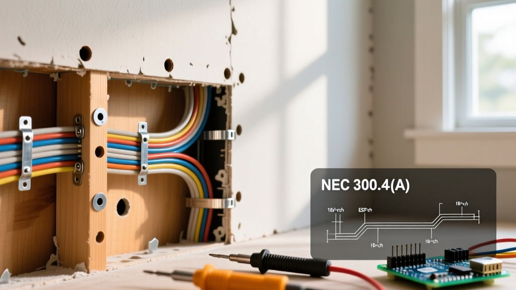
- Check Routing and Separation: Low-voltage I2C lines running to the LCD screen must be routed in separate wire ducts from 120V AC lines or 24V DC motor control lines. If crossing is unavoidable, the wires must cross at a 90-degree angle to minimize inductive coupling.
- Validate Strain Relief: The Belden shielded cable running to the LCD screen must have proper strain relief. If the LCD is mounted on the enclosure door, a hinged cable management loop or a dedicated strain-relief gland must be used to prevent wire fatigue when the door is opened and closed.
- Confirm Grounding and Shielding: The shield of the I2C cable must be grounded at one end only (typically at the DIN-rail terminal block near the Arduino) to prevent ground loops. Connecting the shield at both the Arduino and the LCD screen can create a loop that acts as an antenna for EMI.
Common Failure Modes in Custom Arduino LCD Panels
Beyond passing the initial physical inspection, the wiring must be robust enough to survive the electrical noise of a commercial facility. Here are the most frequent edge cases and failure modes observed in the field:
I2C Bus Lockups Due to VFD Noise
If your Arduino and LCD are mounted in a panel alongside Variable Frequency Drives (VFDs), the high-frequency switching noise can easily couple into unshielded I2C lines. This causes the PCF8574T I2C backpack to misinterpret clock pulses, leading to frozen LCD screens or complete microcontroller lockups. Solution: Always use shielded twisted-pair cable for SDA/SCL lines, and ensure 4.7kΩ pull-up resistors are physically located as close to the Arduino SDA/SCL pins as possible, rather than relying on the backpack's surface-mount resistors.
Backlight Voltage Drop and Flickering
A standard 20x4 LCD backlight can draw up to 120mA. If wired using 28 AWG jumpers over a distance of 50cm, voltage drop will cause the backlight to flicker, especially when the Arduino toggles high-current relays. Solution: Use 22 AWG wire for the VCC and GND lines to the LCD. For runs exceeding 30cm, power the LCD backlight from a dedicated local 5V regulator rather than pulling all current through the Arduino's onboard 5V pin.
Expert FAQ: Navigating Inspector Pushback
Q: The inspector said my Arduino isn't 'listed' for industrial use. How do I proceed?
A: This is a common hurdle. The Arduino Mega 2560 itself is not UL-listed as an industrial controller. To pass a UL 508A panel inspection, the Arduino must be treated as a 'component' rather than a certified safety device. You must ensure that if the Arduino fails, it cannot cause a hazardous condition (e.g., it should not directly switch a 480V motor contactor). Use the Arduino to trigger isolated, UL-listed interposing relays (like the Phoenix Contact PLC-RSC series) that handle the actual load. Document this fail-safe architecture in your panel schematics for the inspector.
Q: Can I use soldered connections for the LCD screen wiring inside the panel?
A: While NEC Article 725 doesn't explicitly ban soldering for low-voltage Class 2 circuits, UL 508A panel shop standards heavily discourage it for field-modifiable or high-vibration environments due to the risk of cold solder joints and lack of visual inspection reliability. The industry best practice in 2026 is to use solderless PCB terminal blocks (like the Wurth Elektronik WR-TBL series) mounted to your custom Arduino shield, allowing for secure, inspectable screw or spring-cage terminations.
Final Thoughts on Documentation
Compliance is as much about paperwork as it is about physical wiring. Always maintain a detailed Bill of Materials (BOM) that includes the UL file numbers for your power supplies, terminal blocks, and wire types. Keep a printed schematic inside the panel door that clearly delineates the Class 2 low-voltage wiring from the primary power circuits. By treating your lcd screen arduino wiring with the same rigor as a high-voltage PLC installation, you ensure safety, reliability, and a smooth inspection process every time.