
The Hidden Dangers of In-Wall Electrical Routing
Every year, the U.S. Consumer Product Safety Commission (CPSC) reports tens of thousands of home fires linked to electrical distribution systems. A significant percentage of these incidents stem from compromised in-wall wiring—specifically, cables that are improperly routed, inadequately protected, or punctured by drywall screws and cabinetry fasteners. When planning an electrical wiring wall layout, electricians and DIYers must look beyond simple circuit connectivity and prioritize physical protection and thermal management.
As we navigate the 2026 construction landscape, material costs for copper NM-B (Non-Metallic Sheathed) cable remain volatile, with a 250-foot spool of Southwire 12/2 NM-B averaging between $110 and $125. Because the financial stakes of a failed rough-in are high, mastering the National Electrical Code (NEC) requirements for framing clearances is non-negotiable. This guide breaks down the exact measurements, failure modes, and safety best practices required to keep your in-wall wiring secure.
The 1.25-Inch Setback Rule: NEC 300.4 Explained
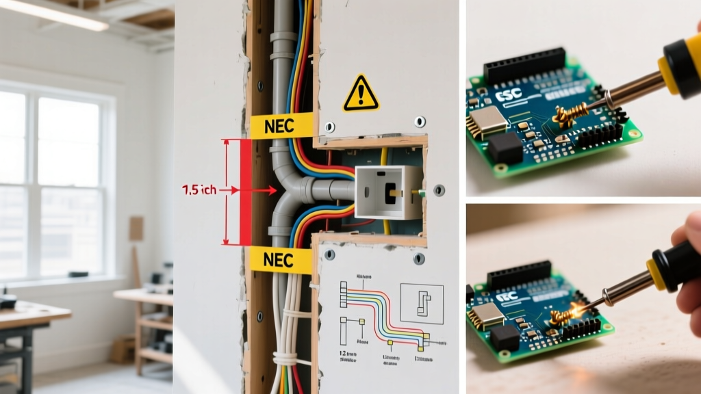
The most frequently violated safety standard in residential rough-ins is the clearance between the edge of a framing member and the bored hole. According to National Fire Protection Association (NFPA) guidelines under NEC Article 300.4(A)(1), cables and raceways installed through bored holes in joists, rafters, or studs must maintain a minimum distance of 1.25 inches (32 mm) from the nearest edge of the framing member.
Why 1.25 Inches? Standard drywall screws are typically 1.25 to 1.625 inches long. When a drywaller or cabinet installer drives a fastener into a stud, the 1.25-inch setback ensures the screw tip cannot reach the cable jacket, preventing catastrophic puncture faults.
When You Cannot Meet the Setback: Nail Plates
In older homes with narrow 2x4 studs (which are actually 1.5 inches wide), or when routing multiple cables through a single stud, maintaining the 1.25-inch edge clearance is sometimes physically impossible. In these scenarios, NEC 300.4(A)(2) mandates the use of a steel nail plate.
- Material: Must be steel (plastic or aluminum plates are not code-compliant for this purpose).
- Thickness: Minimum 1/16 inch (1.6 mm) thick.
- Recommended Product: Arlington Industries BP18 or BP18F nail plates. These retail for approximately $0.45 to $0.60 each in 2026 and feature pronged teeth that hammer directly into the stud without requiring separate screws.
Stud Boring and Notching Limits
Drilling holes in load-bearing studs compromises structural integrity if done incorrectly. The placement of your bored holes dictates both the safety of the electrical wiring wall cavity and the structural soundness of the framing. Below is the definitive matrix for boring and notching wood studs based on IRC and NEC standards.
| Action | Load-Bearing Studs | Non-Load-Bearing Studs | Safety / Code Constraint |
|---|---|---|---|
| Max Hole Diameter | 40% of stud depth | 60% of stud depth | For a standard 2x4 (1.5" wide), max hole is 0.6" (bearing) or 0.9" (non-bearing). |
| Max Notch Depth | 25% of stud depth | 40% of stud depth | Notching the edge of a load-bearing stud for cable routing is strictly prohibited in the middle third of the span. |
| Hole Location | Minimum 5/8" from edge | Minimum 5/8" from edge | Violating the 5/8" edge rule requires a 1/16" steel nail plate. |
Pro Tip: Use a self-feed auger bit like the Greenlee 555 Speed Borer or Milwaukee M18 Fuel Switch Drive auger bits. These pull through wood cleanly without splintering the back edge of the stud, which can create sharp burrs that slice NM-B cable jackets during the pull.
Cable Securing and Support (NEC 334.30)
An electrical wiring wall is not just about where the cable goes, but how it is held in place. Loose cables can sag, rub against rough wood grain, or be pulled taut when a receptacle is serviced, leading to terminal loosening and arcing.
Stapling Requirements
NM-B cable must be secured within 12 inches of every single-gang box (without internal cable clamps) and at intervals not exceeding 4.5 feet. For boxes with internal clamps, the first staple must be within 8 inches.
- Best Practice Staple: Gardner Bender GS-26 (1/2-inch, 50-pack, ~$4.50). These feature a wide crown that secures the cable without pinching the dielectric insulation.
- Failure Mode to Avoid: Never use a hammer to drive wire staples. A glancing blow will easily slice the PVC jacket and nick the copper conductor. Always use a dedicated staple gun (like the Arrow T25) or hand-set the staple and tap it gently with a flat-head hammer.
The Silent Killer: Series Arcing and AFCI Protection
If a drywall screw nicks the side of a 12 AWG hot wire, it rarely causes an immediate short circuit that trips a standard thermal-magnetic breaker. Instead, it creates a high-resistance connection. As current flows, the nicked area heats up, carbonizes the surrounding wood and PVC, and eventually creates a series arc fault.
As highlighted by the Electrical Safety Foundation International (ESFI), arc faults are a leading cause of electrical fires. To mitigate this, the NEC requires Arc Fault Circuit Interrupter (AFCI) protection on almost all 15A and 20A 120V branch circuits supplying bedrooms, living rooms, and kitchens.
- 2026 Standard: Combination-type AFCI breakers (e.g., Square D HOM120CAFIC, retailing around $52-$58) detect both parallel and series arcs down to 5 amps.
- Dual Function (DF) Breakers: For kitchens and bathrooms where GFCI is also required, use DF breakers (like the Eaton BRN120DF) to provide both arc-fault and ground-fault protection directly at the panel, saving wall space.
Low Voltage vs. Line Voltage Separation
Modern electrical wiring wall cavities are crowded. You are likely running 120V AC line voltage alongside Cat6 Ethernet, coaxial, and smart home low-voltage wiring. NEC Article 300.3(C)(1) strictly prohibits running low-voltage and line-voltage conductors in the same bored hole or enclosure unless separated by a permanent barrier.
The 2-Inch Rule: Maintain a minimum 2-inch physical separation between line voltage NM-B cables and low-voltage data cables when running them parallel through studs. If they must cross, do so at a 90-degree angle to minimize electromagnetic interference (EMI) and prevent inductive heating.
Pre-Drywall Inspection Checklist
Before the insulation crew arrives or the drywall goes up, conduct this rigorous safety audit of your wall cavities:
- Verify Setbacks: Measure all bored holes. If any are within 1.25 inches of the stud edge, install 1/16" steel nail plates immediately.
- Check Cable Slack: Ensure at least 3 inches of cable extends past the face of the electrical box, with a minimum of 1/4 inch of jacket pulled inside the box.
- Inspect for Jacket Damage: Run your fingers along the NM-B jacket where it passes through metal studs or tight wood knots. Look for micro-tears.
- Confirm Staple Placement: Verify staples are within 12 inches of the box and not overdriven (which crushes the conductors and alters the dielectric properties of the insulation).
- Fireblocking Penetrations: If cables pass through top plates or fireblocks, seal the gaps with fire-rated expanding foam (e.g., Great Stuff Fireblock, ~$8.50 per can) to prevent the wall cavity from acting as a chimney during a fire.
Final Thoughts on Wall Cavity Safety
Treating the electrical wiring wall as a controlled environment rather than a hidden dumping ground for cables is the hallmark of a master electrician. By strictly adhering to the 1.25-inch setback rule, utilizing proper steel nail plates, and ensuring robust AFCI protection, you eliminate the vast majority of mechanical and thermal failure modes. Always consult the latest NEC cycle and your local Authority Having Jurisdiction (AHJ) before closing up walls, as local amendments can sometimes exceed national baselines.