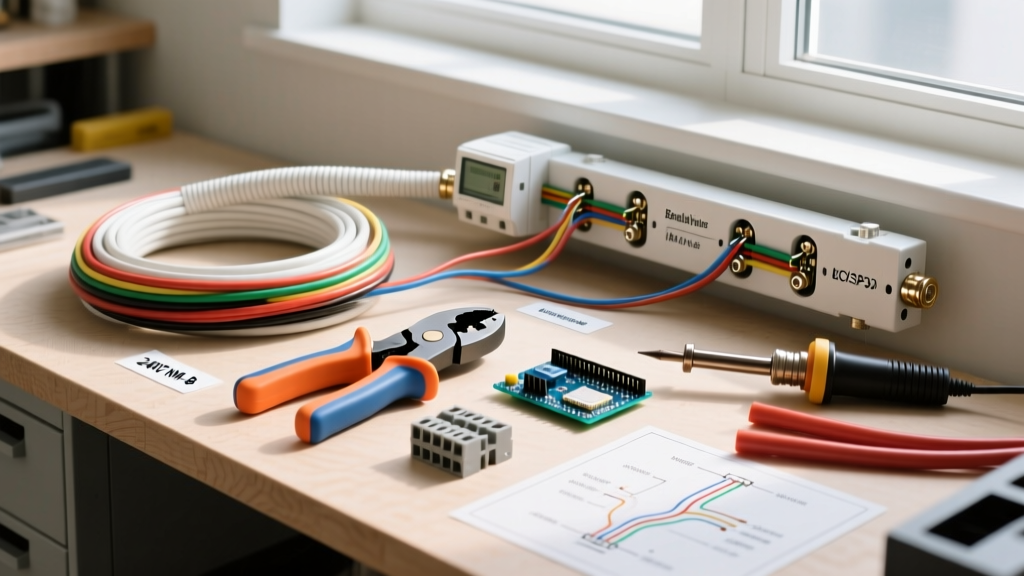

Introduction to 240V Baseboard Thermostat Wiring
Wiring an electric baseboard heater thermostat requires a precise understanding of resistive load calculations, continuous duty cycles, and 240-voltage safety protocols. Unlike standard 120V receptacle wiring, electric baseboard heaters draw substantial, continuous amperage. A poorly executed termination or an undersized cable can lead to thermal degradation, arcing, or catastrophic failure. This material and tool guide provides a comprehensive, professional-grade blueprint for selecting the correct components and executing a flawless installation in compliance with the 2026 National Electrical Code (NEC).
Critical Safety Directive: Electric baseboard heaters operate on 240V dual-pole circuits. Always verify the absence of voltage using a CAT III rated multimeter before touching any conductors. According to the Consumer Product Safety Commission (CPSC), improper handling of 240V circuits is a leading cause of residential electrical fires.
Phase 1: Load Calculation & Material Sizing
Before purchasing materials, you must calculate the exact amperage requirements. The National Fire Protection Association (NFPA 70) classifies space heating equipment as a continuous load, meaning the circuit must be sized at 125% of the heater's maximum draw.
The 125% Continuous Load Formula
- Step 1 (Find Amps): Total Wattage / 240V = Base Amps.
- Step 2 (Apply 125% Rule): Base Amps x 1.25 = Minimum Circuit Ampacity.
- Example: Two 1,500W baseboard heaters daisy-chained = 3,000W. 3,000W / 240V = 12.5A. 12.5A x 1.25 = 15.62A.
- Material Result: A 15.62A requirement mandates a 20-Amp double-pole breaker and 12/2 NM-B (Romex) copper cable. Using 14/2 NM-B on this circuit is a direct NEC violation and a severe fire hazard.
Phase 2: Core Material Selection
Line-Voltage Thermostats: Single-Pole vs. Double-Pole
When wiring an electric baseboard heater thermostat, choosing between single-pole and double-pole models dictates both safety and code compliance. The U.S. Department of Energy recommends programmable or high-accuracy line-voltage thermostats to optimize energy consumption in zone-heated rooms.
| Feature | Single-Pole Thermostat (e.g., Cadet BTF1W) | Double-Pole Thermostat (e.g., Cadet BTF2W) |
|---|---|---|
| Disconnect Level | Breaks one 120V leg (Heater remains energized at low limit) | Breaks both 120V legs (True 240V disconnect) |
| Wire Terminals | 2 (Line and Load) | 4 (Line 1, Line 2, Load 1, Load 2) |
| 2026 Avg. Cost | $22.00 - $28.00 | $32.00 - $45.00 |
| Code Preference | Restricted in some local jurisdictions | Universally accepted; recommended for safety |
Cabling and Connectors
- 12/2 NM-B Cable with Ground: The standard for 20A, 240V residential branch circuits. In 2026, copper pricing fluctuates, but expect to pay approximately $0.65 to $0.85 per foot for high-quality US-manufactured NM-B.
- Wire Nuts: Do not use standard nylon wire nuts for 240V heater connections if the wire count exceeds two 12 AWG solid conductors. Use UL-listed, copper-crimped or high-temperature ceramic wire nuts (e.g., Ideal 341 Blue or equivalent) rated for high-amperage resistive loads to prevent thermal melting.
- Non-Metallic Cable Clamps: Required at the wall box entry point to secure the NM-B jacket and prevent the sharp box edges from slicing the conductor insulation over time.
Phase 3: The Professional Tool Arsenal
Standard DIY toolkits are insufficient for 240V baseboard installations. The following tools ensure safe, code-compliant terminations:
- Fluke 117 True-RMS Digital Multimeter (~$210): Essential for verifying 240V across both hot legs and confirming 0V to ground. Non-contact voltage testers (like the Fluke 1AC-II) are useful for initial sweeps but cannot confirm phase-to-phase voltage or phantom voltages.
- Klein Tools 11063W 8-22 AWG Wire Stripper (~$28): Precision stripping is critical. Nicks in 12 AWG solid copper create micro-fractures that become high-resistance hot spots under continuous 16A loads.
- Wiha 32005 Insulated Screwdriver Set (~$35): VDE-certified insulated screwdrivers protect against accidental contact with live terminal screws when testing thermostat limit switches.
- Leatherman Surge or Heavy-Duty Side Cutters: For cleanly shearing 12 AWG copper and trimming the NM-B outer sheath without scoring the inner THHN insulation.
Phase 4: Execution & Wiring Workflow
Follow this precise workflow to ensure a secure, long-lasting installation.
Step 1: Box Preparation & Cable Entry
Mount a 2-gang or 4-square electrical box (depending on the thermostat manufacturer's volume requirements) at the desired height, typically 60 inches from the finished floor to accurately read the room's ambient thermal stratification. Feed the 12/2 NM-B supply cable and the 12/2 load cable (running to the baseboard heater) into the box. Secure both with internal cable clamps, leaving exactly 1/4 inch of exposed THHN insulation outside the clamp.
Step 2: Grounding Infrastructure
Splice the bare copper ground wires from the supply and load cables together with a 12 AWG pigtail. Connect the pigtail to the green grounding screw in the metal box (if applicable) and the green grounding screw on the thermostat's mounting strap. Never daisy-chain grounds through the thermostat's internal circuitry.
Step 3: Thermostat Termination (Double-Pole Example)
Double-pole thermostats feature four terminal screws, typically color-coded or clearly labeled 'LINE' and 'LOAD'.
- Connect the black and white supply wires (re-identify the white wire with black electrical tape or heat shrink to denote it as a hot 120V leg) to the two 'LINE' terminals.
- Connect the black and white load wires (again, re-identifying the white wire) to the two 'LOAD' terminals.
- Torque the terminal screws firmly. A loose connection on a 240V circuit will arc, generating extreme heat that will melt the thermostat housing within weeks.
Phase 5: Edge Cases & Common Failure Modes
The 'Off' Position Illusion (Single-Pole Hazard)
Homeowners often assume that turning a single-pole thermostat to the 'Off' position completely de-energizes the baseboard heater. In reality, a single-pole thermostat only breaks one leg of the 240V circuit. The heating elements remain energized at 120V to ground. If a homeowner attempts to clean the heater fins or remove a jammed object while the single-pole thermostat is 'off', they risk a lethal shock. Always recommend double-pole thermostats for true disconnect.
Wire Nut Thermal Degradation
Resistive loads generate harmonic heat. If a wire nut is not twisted tightly enough, or if the wires were stripped too short and the copper isn't fully seated inside the metal coil of the nut, the connection resistance increases. Over a 3-year period, this micro-arcing will carbonize the plastic wire nut, eventually causing a short circuit. Always perform a 'tug test' on every wire nut and wrap the base with 3M Super 33+ vinyl electrical tape for added thermal insulation and mechanical support.
Phantom Voltage on Digital Multimeters
When testing a disconnected load wire running to a baseboard heater, a high-impedance digital multimeter may read 40V to 90V. This is 'phantom' or 'ghost' voltage induced by the adjacent live 120V leg in the NM-B cable. Do not mistake this for a live circuit. Use a low-impedance (LoZ) setting on your multimeter, or connect a solenoid voltage tester (wiggy) to bleed off the capacitive coupling and confirm the true absence of lethal voltage.
Conclusion
Successfully wiring an electric baseboard heater thermostat hinges on respecting the physics of continuous 240V resistive loads. By calculating amperage correctly, selecting double-pole thermostats, utilizing 12/2 NM-B cabling, and employing professional-grade testing tools, you ensure a heating system that is both highly efficient and rigorously safe. Always consult your local Authority Having Jurisdiction (AHJ) regarding specific permit requirements and local amendments to the NEC before energizing any new 240V branch circuit.