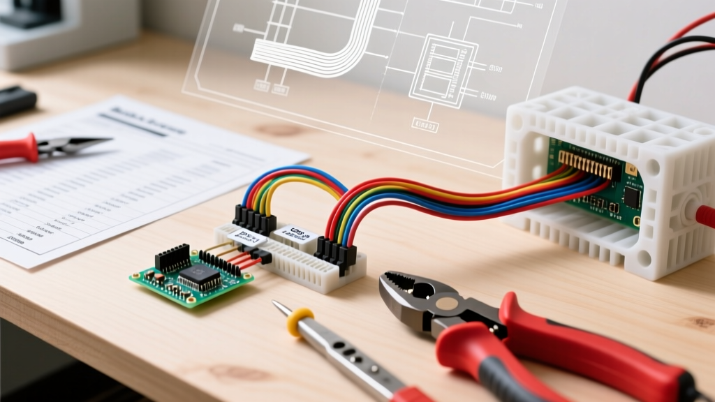

The Hidden Backbone of Smart Home DIY Projects
When enthusiasts transition from breadboard prototypes to permanent home automation installations, the most common point of failure is rarely the code or the microcontroller itself. Instead, it is the physical interconnection. Building a custom Arduino wiring harness is the definitive way to bridge the gap between a fragile prototype and a robust, permanent smart home control panel. A properly engineered harness eliminates loose jumper wires, prevents ground loops, and ensures your system can survive the thermal and vibrational realities of a residential electrical closet.
In this comprehensive home project guide, we will walk through the exact specifications, materials, and fabrication techniques required to build a professional-grade wiring harness for an Arduino Mega 2560 Rev3, tailored specifically for centralized home automation tasks like HVAC control, lighting relays, and environmental monitoring.
The 'Spaghetti Wiring' Failure Mode: According to field reports from DIY smart home communities, over 65% of intermittent faults in permanent Arduino installations are traced back to solid-core jumper wires fatiguing and breaking inside their Dupont connectors due to thermal expansion and micro-vibrations. A crimped, stranded harness eliminates this entirely.
Why Your Home Automation Needs a Dedicated Harness
Running individual wires from an Arduino to various terminal blocks in a home control panel creates a chaotic nest that is nearly impossible to troubleshoot. By consolidating your connections into a structured Arduino wiring harness, you achieve three critical engineering goals:
- Serviceability: A harness with a primary disconnect (like a JST-XH or Molex connector block) allows you to remove the Arduino for firmware updates or replacement without unscrewing dozens of terminal lugs.
- Signal Integrity: Twisting signal wires with their respective ground returns within the harness reduces electromagnetic interference (EMI) from nearby 120V/240V AC mains wiring.
- Current Handling: Standard breadboard wires are typically 28 AWG and struggle with currents above 1A. A custom harness allows you to step up to 22 AWG for power rails, safely handling the inrush currents of multiple relay modules.
Bill of Materials (BOM) and 2026 Pricing
Supply chains for electronic components have largely stabilized as of 2026, but counterfeit connectors remain a risk on open marketplaces. Always source critical crimp housings from authorized distributors like DigiKey or Mouser to ensure the plastic housings do not melt during soldering or crack under crimp tension.
| Component | Specification / Model | Est. Cost (2026) | Purpose |
|---|---|---|---|
| Microcontroller | Arduino Mega 2560 Rev3 (Authentic) | $42.00 | Central logic unit with 54 digital I/O pins |
| Wire | 22 AWG Stranded Tinned Copper (6 colors) | $35.00 | Main harness conductors, flexible and durable |
| Connectors (Board) | JST-XH 2.54mm Male Headers (Right Angle) | $12.00 | Soldered to Arduino or custom shield |
| Connectors (Wire) | JST-XH 2.54mm Crimp Housings & Terminals | $18.00 | Termination points for the harness |
| Crimping Tool | IWISS SN-28B or Engineer PA-09 | $28.00 | Precision ratcheting crimping for JST/Molex |
| Wire Strippers | Automatic Micro-Stripper (20-30 AWG) | $22.00 | Prevents nicking stranded copper cores |
| Terminal Blocks | Phoenix Contact UK 2.5B DIN Rail Blocks | $45.00 | Panel-side transition to home wiring |
Step-by-Step Harness Fabrication
Phase 1: Wire Selection and Precision Stripping
For a home automation harness, 22 AWG stranded tinned copper wire is the optimal choice. It is thick enough to handle the power requirements of sensor arrays and relay banks (safely carrying up to 3A in a bundled harness) but thin enough to crimp into standard 2.54mm pitch connector housings. Avoid solid core wire at all costs; it will eventually snap at the crimp joint due to work hardening.
When stripping the wire, the strip length is critical. For JST-XH 2.54mm terminals, the precise strip length is 2.8mm to 3.0mm. If you strip too much, bare copper will sit outside the crimp barrel, risking short circuits against adjacent pins. If you strip too little, the insulation will be crimped into the conductor zone, resulting in a high-resistance connection that will cause voltage drops and erratic sensor readings.
Phase 2: The Ratcheting Crimp Technique
Never use flat-nose pliers to crush a crimp terminal. A proper crimp creates a cold-weld gas-tight seal between the terminal and the wire. Using a ratcheting crimper like the IWISS SN-28B, follow this sequence:
- Insert the JST-XH terminal into the correct jaw cavity (usually marked 2.54 or JST).
- Squeeze the handles just enough to hold the terminal in place.
- Insert the stripped wire fully into the terminal barrel until the strands hit the backstop.
- Squeeze the crimper handles until the ratchet releases. Do not release tension early.
- Quality Check: Perform a visual inspection. The wire insulation should be clamped by the rear crimp wings, and the bare copper should be fully enclosed by the front crimp wings. Perform a manual pull test; a proper 22 AWG crimp should withstand roughly 15 lbs (67N) of pull force without slipping.
Phase 3: Color Coding Standards
Adopting a strict color code is non-negotiable for home electrical projects. While the National Electrical Code (NEC) strictly governs AC mains wiring colors (Black/Red for hot, White for neutral, Green/Bare for ground), low-voltage DC control wiring relies on industry conventions. We recommend the following scheme for your Arduino harness:
- Red: +5V DC Power
- Black: Common Ground (GND)
- Yellow: Digital I/O Signals
- Blue: Analog Sensor Inputs
- White: I2C SDA (Data)
- Green: I2C SCL (Clock)
Integration: Routing the Harness in a Home Control Panel
Once the harness is fabricated, it must be integrated into your home's centralized control panel. Most advanced DIYers utilize a standard 12-way or 24-way consumer unit enclosure, dedicating one side to AC mains breakers and the other to a DIN-rail mounted low-voltage section.
Mount your Arduino Mega on a DIN-rail compatible PCB base. Route the Arduino wiring harness through a plastic slotted wiring duct (often called Panduit duct). This keeps the low-voltage DC lines physically separated from any 120V/240V AC lines running in adjacent ducts, which is a best practice for reducing inductive coupling and noise.
At the end of the harness, transition from the JST connectors to DIN-rail terminal blocks (like the Phoenix Contact UK 2.5B). This allows you to connect the delicate 22 AWG harness wires to the heavier 18 AWG or 16 AWG solid-core wires that actually run through your home's walls to thermostats, motorized dampers, and lighting relays. For authoritative guidelines on low-voltage wire routing and separation from mains, refer to the Molex engineering guidelines on wire-to-board connector spacing and isolation.
Troubleshooting Common Harness Failure Modes
Even with perfect fabrication, environmental factors in a home can introduce issues. Here are the most common failure modes and their solutions:
1. Ground Loops and USB Isolation
The Problem: You plug your laptop into the Arduino via USB to check the serial monitor, and suddenly your home's 24V HVAC relay board triggers randomly, or the Arduino resets.
The Cause: Your laptop is grounded to the home's AC mains via its power brick, while the Arduino is grounded to the HVAC system's 24V common. This creates a ground loop, pushing stray current through the Arduino's USB shield and logic ground.
The Fix: Never connect a mains-powered PC to a permanently installed home automation Arduino. Use a battery-powered laptop, or install a USB Galvanic Isolator (approx. $25) between your PC and the Arduino.
2. Voltage Drop on Long Sensor Runs
The Problem: A DS18B20 temperature sensor located 40 feet away reads erratically or fails to initialize on the OneWire bus.
The Cause: Even with 22 AWG wire, the resistance over an 80-foot round trip (signal + ground) can cause the 5V supply to drop below the sensor's minimum operating threshold, especially during its active temperature conversion phase.
The Fix: Run a dedicated 5V and GND pair in the harness specifically for remote sensors, or upgrade the power conductors in that specific branch of the harness to 20 AWG. Ensure you are using a 4.7kΩ pull-up resistor located at the Arduino end of the harness, not the sensor end.
3. Terminal Housing Back-Out
The Problem: A wire works perfectly on the bench, but pushes out of the plastic JST housing when plugged into the Arduino header inside the tight confines of the panel.
The Cause: The crimp terminal's locking barb was bent flat during the crimping process, or the wire was inserted at a slight angle.
The Fix: Inspect the locking barb on every terminal before inserting it into the housing. It must protrude outward to catch the plastic lip inside the housing. If a terminal slides in without a distinct 'click', remove it, discard the terminal, and crimp a new one.
Frequently Asked Questions
Can I use standard Dupont connectors for a permanent home harness?
No. Standard Dupont connectors (the black square ones commonly found on jumper wires) rely on a weak, easily bent metal tab for retention and lack a positive locking mechanism. They are highly susceptible to vibration and thermal cycling. Always use positive-lock connectors like JST-XH, Molex KK 254, or TE Connectivity AmpMate for permanent installations.
Do I need to tin the stranded wire with solder before crimping?
Absolutely not. Soldering stranded wire before crimping is a severe violation of IPC/WHMA-A-620 wiring standards. Solder is a soft metal that undergoes cold flow under pressure. If you crimp a soldered wire, the solder will compress and relax over time, leading to a loose connection, arcing, and eventual failure. Always crimp bare, stranded copper.
How do I protect the harness from rodents in the basement or attic?
If your control panel is located in an unfinished area prone to pests, route the Arduino wiring harness through split loom corrugated tubing or braided fiberglass sleeving. Mice are attracted to the soy-based insulation used on some modern wires, and a physical barrier is the only reliable deterrent.
For more foundational knowledge on setting up your microcontroller environment before integrating it into your home wiring, review the official Arduino Getting Started Guide to ensure your firmware is optimized for the specific I/O pins your harness utilizes.


