
Integrating Analog Controls in Modern Smart Home Renovations
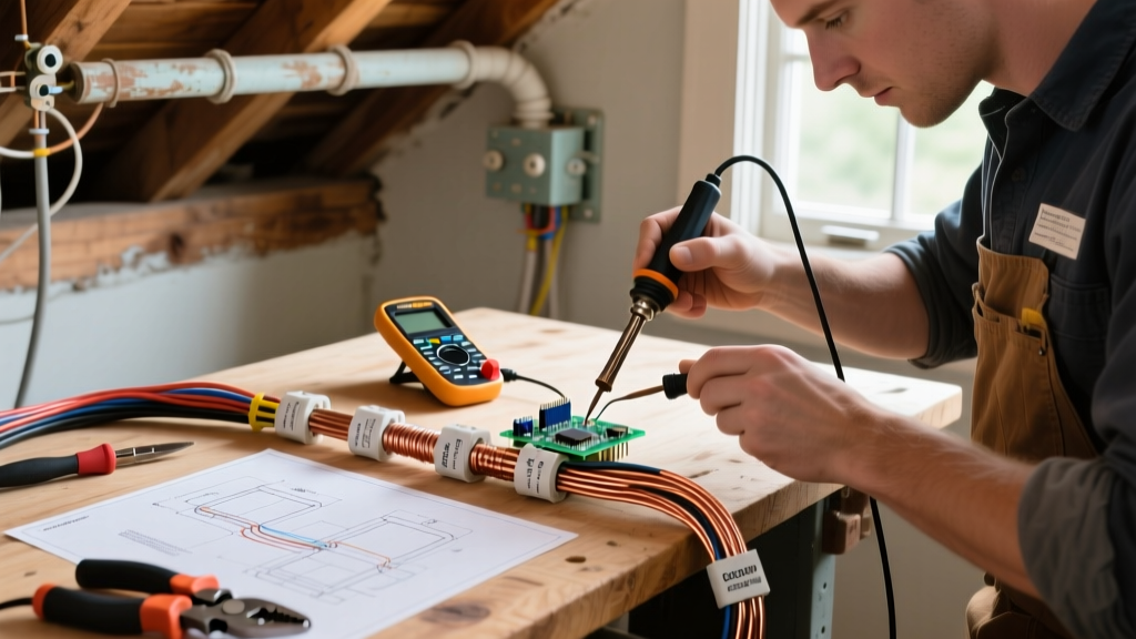
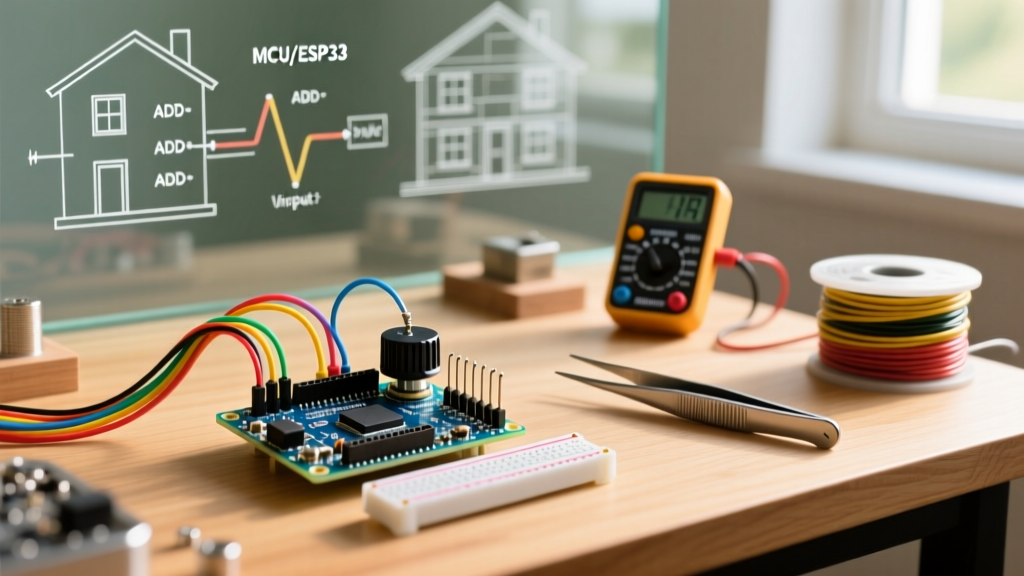
As we move through 2026, high-end home renovations are increasingly rejecting app-only interfaces in favor of tactile, hardwired analog controls. Whether you are building a custom motorized shade controller, a zero-latency PWM LED dimmer, or a bespoke HVAC damper system, mastering potentiometer wiring Arduino architectures is essential for reliable, physical user interfaces. Unlike capacitive touchscreens, a physical rotary knob provides immediate muscle-memory feedback and operates independently of network latency.
However, integrating low-voltage DC microcontroller components into standard residential wall boxes introduces distinct electrical and mechanical challenges. This guide provides a deep-dive, electrician-grade approach to specifying, wiring, and troubleshooting potentiometer circuits for Arduino-based renovation projects, ensuring your custom control panels are both responsive and code-compliant.
Component Selection: Matching Specs to Your Renovation
Not all potentiometers are created equal. For wall-mounted renovation projects, you must select components that withstand daily mechanical stress and match the electrical impedance of your microcontroller's Analog-to-Digital Converter (ADC).
Recommended Panel-Mount Potentiometers
- Alpha RD901F-40-15K1-B10K: A premium 10k Ohm linear taper panel-mount pot. Features a 15mm D-shaft and built-in dust cover. Priced around $2.80 per unit, it offers a smooth 300-degree mechanical rotation ideal for lighting dimmers.
- Bourns PDB181-GTR01-103C2: A 10k Ohm guitar-style potentiometer with a built-in push-pull switch. Excellent for combined power-toggle and speed-control applications (e.g., turning on a custom exhaust fan while simultaneously setting its RPM). Costs approximately $4.50.
Why 10k Ohm is the Renovation Standard
While 50k and 100k potentiometers draw less standby current, they possess higher internal resistance. In a renovation environment where wire runs between the wall switch and the central microcontroller hub can exceed 15 feet, high-impedance pots act as antennas, picking up 60Hz electromagnetic interference (EMI) from adjacent AC mains wiring. A 10k Ohm potentiometer provides a low-impedance path that drastically reduces ADC sampling noise while keeping current draw to a negligible 0.33mA at 3.3V.
Understanding Tapers: Linear vs. Logarithmic
Choosing the wrong taper is the most common reason custom smart-home dimmers feel 'broken' to the end-user. The taper dictates how the resistance changes relative to the shaft rotation.
| Taper Type | Marking Code | Best Renovation Application | Behavior Profile |
|---|---|---|---|
| Linear | B (e.g., B10K) | Motorized blinds, HVAC dampers, PID tuning | Resistance changes at a constant rate. 50% rotation = 50% voltage. |
| Logarithmic (Audio) | A (e.g., A10K) | LED strip dimming, audio volume control | Resistance changes slowly at first, then rapidly. Matches human eye/ear perception. |
| Reverse Logarithmic | C (e.g., C10K) | Specialized sensor calibration | Opposite of Audio taper. Rarely used in standard wall controls. |
Critical Voltage Matching: 5V vs 3.3V Logic
In 2026, the Arduino Nano ESP32 (retailing around $21.50) is the go-to board for renovation projects due to its integrated Wi-Fi and Bluetooth. However, it operates on 3.3V logic. Standard legacy Arduinos (like the Uno R3) operate on 5V.
WARNING: If you wire a potentiometer's outer pin to a 5V source and connect the wiper to an ESP32 GPIO pin (like GPIO36), you will feed 5V into a 3.3V ADC input. Over time, this will degrade the silicon, cause permanent saturation at the high end of the dial, and potentially destroy the microcontroller pin. Always match your potentiometer's VCC to the microcontroller's logic level.
For a comprehensive overview of how microcontrollers read these voltage drops, refer to the official Arduino AnalogReadSerial documentation, which outlines the foundational mapping of 0-5V (or 0-3.3V) to 10-bit or 12-bit integer values.
Step-by-Step Potentiometer Wiring Arduino Guide
Follow this precise sequence to ensure a clean, noise-free installation inside a standard residential gang box.
- Prepare the Wire Harness: Use 22 AWG stranded silicone wire. Silicone insulation withstands soldering heat without melting back, which is crucial when working in tight wall boxes. Cut three lengths of wire (Red for VCC, Black for GND, Yellow for Wiper) long enough to reach your central hub plus 12 inches of slack.
- Solder the Potentiometer Pins: Tin the three lugs on the Alpha RD901F. Solder Red to Pin 1 (CCW), Black to Pin 3 (CW), and Yellow to Pin 2 (Wiper). Note: Reversing Pin 1 and Pin 3 simply reverses the rotation direction in software, but standardizing CW-as-increasing is best practice.
- Apply Heat Shrink and Shielding: Slide 3mm heat shrink over each solder joint. For runs longer than 5 feet, wrap the three wires in copper foil tape or use a braided shield, grounding the shield only at the microcontroller end to prevent ground loops.
- Terminate at the Microcontroller: Connect Red to 3.3V, Black to GND, and Yellow to your designated ADC pin (e.g., A0 on a Nano Every, or GPIO36 on an ESP32).
Signal Conditioning & Edge Case Troubleshooting
Even with perfect wiring, raw ADC readings from a potentiometer often fluctuate by 5-15 points due to thermal noise and EMI. To achieve a rock-solid renovation install, implement hardware signal conditioning.
The 0.1µF Capacitor Debounce
Solder a 0.1µF (104) ceramic capacitor directly between the Wiper wire and the GND wire at the microcontroller terminal block. This creates a passive RC low-pass filter. The 10k pot resistance and 0.1µF capacitor yield a cutoff frequency of roughly 159Hz, effectively filtering out high-frequency RF noise and 60Hz mains hum without introducing noticeable latency to the user's physical knob twist.
Edge Case: ADC Non-Linearity at Extremes
Most microcontroller ADCs exhibit slight non-linearity at the absolute bottom (0V) and top (VCC) of their range. In software, map your 12-bit ADC input (0-4095) to a constrained range (e.g., 50-4045) and use a moving average filter of 8 samples to eliminate 'jitter' when the user lets go of the knob.
NEC Compliance for Low-Voltage Renovation Wiring
When routing potentiometer wiring inside walls, you must adhere to the National Electrical Code (NEC). Potentiometer data lines are classified as Class 2 Circuits under NEC Article 725.
- Separation from Mains: Low-voltage DC wires cannot share the same gang box compartment with 120V AC mains wiring unless a physical, listed barrier is installed.
- Box Selection: Use specialized old-work boxes with integrated dividers, such as the Carlon B618R-UPC, which provides a dedicated, isolated chamber for your Arduino wiring harness separate from any adjacent line-voltage smart switch.
- Plenum Ratings: If your wire runs pass through HVAC return air spaces (drop ceilings), you must use CMP (Communications Multipurpose Cable, Plenum) rated wire to prevent toxic smoke propagation in the event of a fire.
Mechanical Mounting in Standard Wall Plates
Mounting a raw potentiometer to drywall is impossible without a faceplate. For a professional 2026 renovation finish, avoid ugly 3D-printed brackets. Instead, purchase a Leviton Decora blank insert (approx. $1.50) and drill a precise 7mm (1/4-inch) hole through the center. The Alpha RD901F shaft will pass through perfectly, allowing you to secure the pot with its included hex nut on the front, and cap it with a standard aluminum D-shaft knob. This yields a commercial-grade, architectural finish that blends seamlessly with standard light switches.
Summary
Successful potentiometer wiring Arduino projects in home renovations require more than just connecting three pins. By selecting the correct 10k linear taper, matching your voltage logic to 3.3V ESP32 architectures, implementing hardware RC filtering, and strictly following NEC Class 2 separation rules, you can build custom tactile interfaces that outlast and outperform commercial off-the-shelf smart home products.