
The Hidden Dangers of Improper Air Handler Wiring
An air handler unit (AHU) is the indoor workhorse of your HVAC system, responsible for circulating conditioned air throughout your home. While the blower motor itself might only draw 5 to 10 amps, the addition of electric resistance heat strips can push the total electrical demand well over 60 amps at 240 volts. Improper air handler electrical wiring is not merely a technical code violation; it is a primary catalyst for residential electrical fires, equipment destruction, and severe arc flash hazards.
In 2026, with the widespread adoption of high-efficiency variable-speed blowers and advanced communicating thermostats, the electrical infrastructure supporting your air handler must be flawless. This guide details the exact safety protocols, National Electrical Code (NEC) requirements, and field-tested best practices required to wire an air handler safely and reliably.
Critical NEC Requirements for Air Handler Circuits
The National Fire Protection Association (NFPA) outlines strict parameters for HVAC equipment under NEC Article 440 (Air-Conditioning and Refrigerating Equipment) and Article 424 (Fixed Electric Heating Equipment). Ignoring these articles is the most common mistake DIYers and junior technicians make.
Code Spotlight: NEC 440.12 Disconnecting Means
A disconnecting means must be located within sight from, and readily accessible from, the air-conditioning or refrigerating equipment. This means you cannot rely solely on the main panel breaker; a dedicated local disconnect switch or breaker lockout is legally required for technician safety.
Line Voltage vs. Heat Strip Circuits
Most modern air handlers require two separate line-voltage circuits if electric heat strips are installed. The blower motor and control board operate on a dedicated 120V or 240V circuit (usually 15A or 20A), while the heat strips require a separate 240V high-amperage circuit. Combining these on a single breaker without calculating the combined Minimum Circuit Ampacity (MCA) will result in immediate nuisance tripping and potential wire melting.
Step-by-Step Safety Protocol: Power Off to Termination
Before stripping a single wire, you must establish a verifiable zero-energy state. Relying on a smart thermostat or a wall switch to confirm power is off is a fatal error. Follow the Occupational Safety and Health Administration's (OSHA) guidelines for Lockout/Tagout (LOTO) procedures adapted for residential and light commercial HVAC.
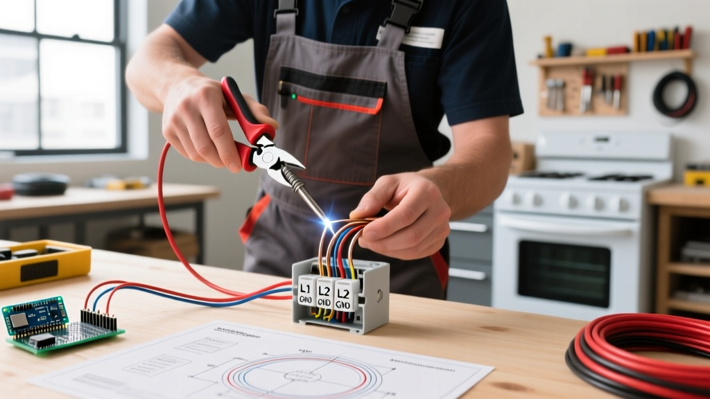
- Shut Off the Main Breaker: Turn off the specific 2-pole breaker for the air handler and the 1-pole breaker for the blower/control circuit at the main service panel.
- Apply LOTO Devices: Use a breaker lockout device (e.g., Klein Tools 89315 LOTO Kit, approx. $48) and apply a physical padlock. If you are working alone, keep the only key on your person.
- Verify with a True-RMS Multimeter: Open the air handler access panel. Use a CAT III or CAT IV rated True-RMS multimeter (such as the Fluke 117, approx. $225) to test between Line 1 and Line 2, Line 1 to Ground, and Line 2 to Ground. All readings must be exactly 0.00V.
- Test the Low-Voltage Side:Verify that the 24VAC transformer secondary side is also dead to ensure no back-feeding is occurring from an external source or a shared thermostat bus.
Wire Sizing and Breaker Matching Matrix
Sizing wire based on the Maximum Overcurrent Protection (MOCP) rather than the Minimum Circuit Ampacity (MCA) is a frequent error. The manufacturer's data plate dictates the exact MCA and MOCP. Below is a standard reference matrix for 240V air handlers with integrated electric heat strips, utilizing copper conductors with 75°C terminations.
| System Configuration | Heat Strip kW | MCA (Amps) | MOCP (Breaker) | Min. Copper Wire Size (NM-B) | Min. Copper Wire Size (THHN) |
|---|---|---|---|---|---|
| 2-Ton Blower Only | 0 kW | 12A | 15A | 14 AWG | 14 AWG |
| 3-Ton + Light Heat | 5 kW | 32A | 40A | 8 AWG | 10 AWG |
| 4-Ton + Medium Heat | 10 kW | 55A | 60A | 6 AWG | 6 AWG |
| 5-Ton + Heavy Heat | 15 kW | 78A | 90A | 4 AWG | 4 AWG |
Note: NM-B (Romex) cable ampacity is strictly limited to the 60°C column of NEC Table 310.15(B)(16), regardless of the 90°C rating of the internal THHN insulation. THHN in conduit can utilize the 75°C or 90°C columns for derating purposes, but the final termination ampacity is still bound by the equipment's rated termination temperature.
Torque Terminations: The 2026 Enforcement Standard
One of the most heavily enforced updates in recent NEC cycles (specifically NEC 110.14(D)) requires that all electrical connections for equipment rated 100 amps or less be tightened to the manufacturer's specified torque using a calibrated torque tool. Hand-tightening wire lugs on an air handler terminal block is no longer acceptable.
Loose connections create high-resistance joints. When a 40-amp heat strip circuit operates with a loose lug, the localized resistance generates immense heat, eventually melting the wire insulation, scorching the terminal block, and causing an arc fault. Invest in an insulated torque screwdriver (e.g., CDI Torque 401SM or Klein Tools 6543-16, approx. $65) and always check the data plate for the required inch-pound (in-lb) rating—typically between 35 and 50 in-lbs for standard HVAC terminal blocks.
Control Wiring: Low-Voltage Safety Separation
Air handlers utilize 24VAC control wiring to communicate with the outdoor condenser and the indoor thermostat. Safety and signal integrity demand strict separation between line voltage and low voltage.
- Physical Separation: Maintain a minimum 1-inch physical gap between 120/240V line conductors and 18 AWG thermostat wires. If they must cross, they should do so at a 90-degree angle.
- Induction Hazards: Running 18/8 solid copper thermostat wire parallel to a 240V heat strip circuit for more than a few feet can induce ghost voltages via capacitive coupling. This can cause solid-state relay boards to misfire or fail prematurely.
- Stranded vs. Solid: While 18 AWG solid wire is standard for thermostat runs, use 18 AWG stranded wire for the final pigtails inside the air handler control box. Stranded wire is far more resistant to the constant micro-vibrations generated by the blower motor, preventing work-hardening and eventual wire snapping.
Common Failure Modes and Edge Cases
Even with correct wire sizing, specific installation environments introduce unique failure modes that demand proactive mitigation:
1. Condensate Drain Pan Overflow Shorting
If the primary PVC condensate drain clogs, water backs up into the secondary drain pan. If the air handler's electrical junction box is mounted below the pan level, or if wire nuts are left resting on the metal floor of the blower compartment, a drain overflow will cause a direct short to ground. Always route wiring high along the side walls of the unit and use a float switch wired in series with the 24V 'Y' (compressor) signal to kill the system before water breaches the electrical zone.
2. Contactor Pitting and Inrush Current
Electric heat strips cycle on and off frequently. The massive inrush current (often 10x the running current for the first few milliseconds) causes micro-arcing at the heavy-duty contactor points. Over 3 to 5 years, this pitting increases resistance. During annual maintenance, inspect the contactor points. If they appear blackened or heavily cratered, replace the contactor immediately (a standard 40A, 240V coil contactor costs roughly $25) before it welds shut, which would cause the heat strips to run continuously and potentially overheat the ductwork.
3. The 'Floating Neutral' in 120V Blower Circuits
For air handlers that utilize a 120V blower motor and a 240V heat strip, the neutral wire is critical. A loose or missing neutral on the 120V side will cause the control board to seek a return path through the equipment grounding conductor (EGC) or the low-voltage thermostat wiring. This will instantly fry the $300+ main control board and pose a severe shock hazard to anyone touching the thermostat. Always verify neutral continuity before applying power.
Frequently Asked Questions
Can I use aluminum wire for my air handler heat strips?
While aluminum wire (like 2-2-2-4 SER cable) is common for main service panels and large outdoor heat pumps, it is highly discouraged for the internal pigtailing of indoor air handler heat strips. The terminal blocks on most indoor HVAC units are not rated for aluminum (AL/CU), and the thermal expansion/contraction cycles of heat strips will quickly loosen aluminum connections, leading to fire hazards. Stick to copper for indoor AHU wiring.
Does the air handler disconnect need to be fused?
Not necessarily. If the branch circuit breaker at the main panel is sized exactly to the manufacturer's specified MOCP (Maximum Overcurrent Protection), a non-fused disconnect switch (e.g., a standard 60A pull-out disconnect) is perfectly legal and provides the required local shut-off. Fused disconnects are only required if the branch breaker is larger than the equipment's MOCP, which is rare in residential retrofits.
Why is my 240V air handler tripping the GFCI breaker?
Modern NEC updates require GFCI protection for many 120V and 240V receptacles and specific hardwired appliances. However, HVAC compressors and certain air handler components can generate harmless leakage current during startup that nuisance-trips standard GFCI breakers. If your local jurisdiction mandates GFCI for the AHU circuit, ensure you are using an HVAC-specific GFCI breaker designed with a higher trip threshold or time-delay to handle motor inrush and compressor leakage without false tripping.
For further reading on HVAC efficiency and electrical load management, refer to the U.S. Department of Energy's heating and cooling guidelines. Proper wiring not only ensures safety but also optimizes the energy performance of your climate control system.