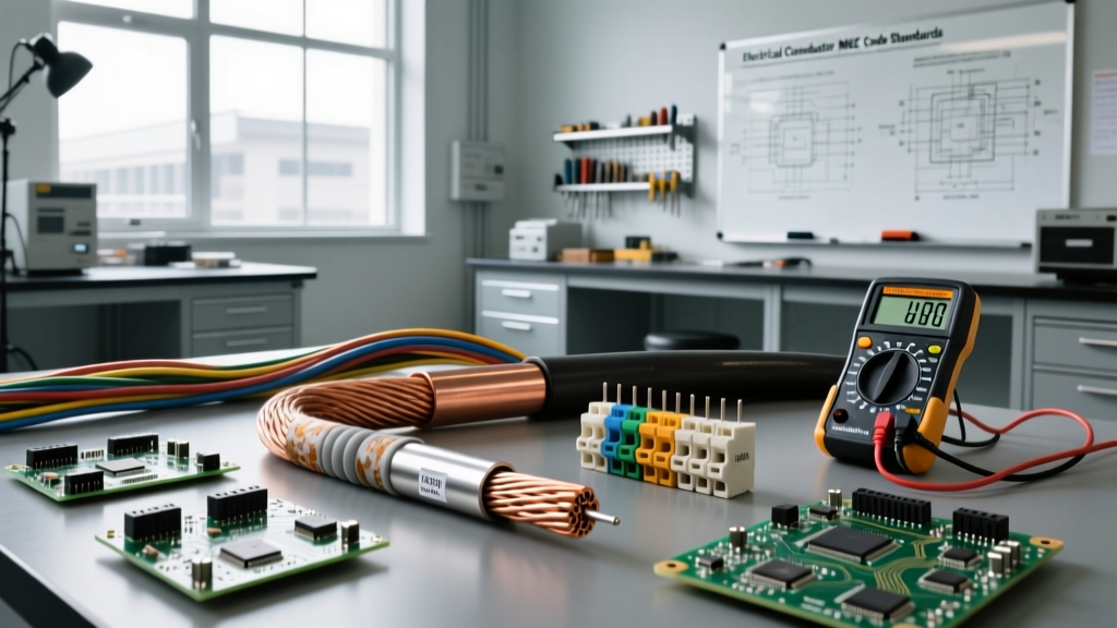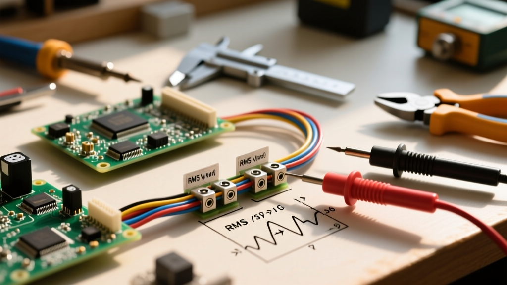

Understanding the mathematics of electricity AC (Alternating Current) is a critical milestone for any DIY electronics enthusiast or apprentice electrician. Unlike Direct Current (DC), where electrons flow in a single, steady direction, electricity AC periodically reverses direction. This oscillation introduces complex variables like phase angles, reactance, and Root Mean Square (RMS) values that completely change how we calculate power and size wires.
In this calculation tutorial, we will break down the essential formulas for AC circuits, moving from basic RMS voltage conversions to advanced AC voltage drop calculations required for proper wire sizing.
The Core Difference: Why Electricity AC Requires Different Math
When you measure a DC circuit, a multimeter reads the exact, constant voltage. However, an AC sine wave is continuously changing from zero to a positive peak, back through zero, to a negative peak, and back again. If you simply averaged these values, the result would be zero. To perform useful work calculations, electrical engineers use the Root Mean Square (RMS) method to find the effective DC-equivalent value of an AC waveform.
Step 1: Calculating RMS (Root Mean Square) Values
In North America, the standard residential wall outlet is rated for 120V AC. This is the RMS voltage, not the peak voltage. The actual peak voltage of electricity AC in a standard US outlet is approximately 170V.
The Peak-to-RMS Conversion Formula
To convert peak voltage to RMS voltage for a pure sine wave, use the following formula:
V_RMS = V_peak / √2 (or V_RMS = V_peak × 0.7071)
Conversely, if you are designing a circuit and need to select capacitors or diodes that can withstand the maximum voltage stress, you must calculate the peak voltage:
V_peak = V_RMS × 1.414
Practical Insight: If you are building a DIY bridge rectifier to convert 120V AC to DC, your smoothing capacitors must be rated for at least 170V (120 x 1.414). Using a standard 150V capacitor will result in a catastrophic dielectric failure and potential explosion.
Step 2: AC Power Calculations (Real vs. Apparent Power)
In DC circuits, power is simply Voltage multiplied by Current (P = V × I). In electricity AC systems, this simple multiplication only yields Apparent Power (measured in Volt-Amps, VA). Because AC circuits often contain inductive loads (like motors and transformers) or capacitive loads, the voltage and current waveforms can fall out of sync, creating a phase shift.
According to Georgia State University's HyperPhysics, this phase shift means that not all the power drawn from the source is converted into useful work.
Understanding the Power Factor (PF)
To find the Real Power (measured in Watts, W) that actually does useful work, you must multiply the Apparent Power by the Power Factor (PF). The PF is a dimensionless number between 0 and 1.
Real Power (W) = V_RMS × I_RMS × PF
| Load Type | Typical Power Factor | Example Appliances | Calculation Impact |
|---|---|---|---|
| Purely Resistive | 1.0 (Unity) | Space heaters, incandescent bulbs, toasters | Watts = VA (No phase shift) |
| Inductive | 0.70 to 0.90 | AC compressors, drill presses, fluorescent ballasts | Watts < VA (Current lags voltage) |
| Capacitive | 0.80 to 0.95 | Switch-mode power supplies, capacitor banks | Watts < VA (Current leads voltage) |
Pro-Tip: When sizing a portable generator or UPS for your workshop, always calculate using Apparent Power (VA), not just Real Power (W). As noted by Fluke Corporation, ignoring the power factor of inductive motors is the number one reason DIYers undersize their backup power systems, leading to tripped breakers during motor startup.
Step 3: Calculating AC Voltage Drop and Wire Sizing
Wire sizing for DC relies purely on the resistance (R) of the conductor. However, electricity AC introduces Reactance (X), which is the opposition to current flow caused by the alternating magnetic fields surrounding the wire. Together, Resistance and Reactance form Impedance (Z).
Z = √(R² + X²)
For standard 60Hz residential wiring, reactance is relatively small, but it becomes significant when sizing large feeders or running wires in steel conduits. The National Electrical Code (NEC) Chapter 9, Table 9 provides AC impedance values that factor in both resistance and inductive reactance.
The AC Voltage Drop Formula
For a single-phase AC circuit, the approximate voltage drop (VD) formula is:
VD = 2 × I × L × (R cosθ + X sinθ) / 1000
- I = Current in Amps
- L = One-way length of the wire in feet
- R = AC Resistance per 1000 feet (from NEC Table 9)
- X = Reactance per 1000 feet (from NEC Table 9)
- cosθ = Power Factor
- sinθ = Reactive Factor (√(1 - PF²))
Real-World Calculation Example: Sizing a 240V AC Compressor Circuit
Let's apply these concepts to a real-world scenario. You are wiring a 240V, single-phase, 20-Amp air compressor located 80 feet from the breaker panel. The motor nameplate specifies a Power Factor of 0.85. The wires will be pulled through PVC conduit.
1. Determine the Reactive Factor:
sinθ = √(1 - 0.85²) = √(1 - 0.7225) = √0.2775 ≈ 0.527
2. Select a Trial Wire Size (10 AWG Copper):
According to All About Circuits and NEC Table 9 for uncoated copper in PVC conduit:
R = 1.2 Ω / 1000ft
X = 0.054 Ω / 1000ft
3. Calculate the Voltage Drop:
VD = 2 × 20A × 80ft × [(1.2 × 0.85) + (0.054 × 0.527)] / 1000
VD = 3200 × [1.02 + 0.028] / 1000
VD = 3200 × 1.048 / 1000
VD = 3.35V
4. Calculate the Percentage Drop:
(3.35V / 240V) × 100 = 1.39%
Conclusion: The NEC recommends a maximum voltage drop of 3% for branch circuits. At 1.39%, 10 AWG copper wire is mathematically sound for this AC voltage drop. However, because the motor draws 20A continuously, NEC Article 210.19 requires the branch circuit to be sized at 125% of the continuous load (25A). Therefore, you must step up to 8 AWG copper wire to satisfy ampacity rules, which will further reduce your voltage drop to a negligible ~0.8%.
Common AC Calculation Mistakes to Avoid
- Using DC Resistance for AC Sizing: While DC resistance is fine for basic 12V automotive or solar calculations, ignoring AC reactance in long 240V+ runs can lead to undersized wires, especially when wires are bundled tightly in metal conduits where magnetic hysteresis increases impedance.
- Ignoring the Skin Effect: At 60Hz, the skin effect (where AC current prefers to travel on the outer surface of the conductor) is negligible for wires smaller than 1/0 AWG. However, if you are calculating feeders for a large subpanel using 250 kcmil or larger cables, the AC resistance is noticeably higher than the DC resistance.
- Assuming Watts = VA on Motor Nameplates: Always look for the FLA (Full Load Amps) and the Power Factor on motor nameplates. Sizing your wire and breaker based purely on the mechanical Horsepower or Wattage output will result in severe undersizing, as you are ignoring the reactive power required to maintain the motor's magnetic field.
Mastering electricity AC calculations bridges the gap between simply following a wiring diagram and truly understanding the physics of your electrical system. By respecting RMS values, power factors, and impedance, you ensure your DIY projects and workshop upgrades are both mathematically optimized and inherently safe.