
The Physics of Failure: Heat, Resistance, and Derating
When discussing conductors and electricity, safety is rarely about the metal itself failing; it is about the thermal and electromagnetic byproducts of current flow. Every conductor possesses inherent resistance. As electrical current (I) flows through this resistance (R), it generates heat proportional to the square of the current ($I^2R$). In a perfectly engineered system, this heat dissipates safely into the ambient environment. In the real world, improper sizing, bundling, and environmental factors turn conductors into heating elements.
The most common safety failure in conductor sizing is ignoring ampacity derating. According to the National Electrical Code (NEC) Table 310.15(C)(1), when you bundle more than three current-carrying conductors in a single raceway or cable, the heat dissipation capability drops drastically. For instance, if you pull nine 12 AWG THHN copper conductors through a single conduit to feed multiple 20A circuits, you must apply a 50% derating factor. The ampacity of that 12 AWG wire drops from 30A (at 90°C) to 15A. If the breaker remains at 20A, the conductor will operate above its thermal limits, slowly degrading the insulation until a phase-to-ground fault or fire occurs.
Material Selection: Copper vs. Aluminum Safety Profiles
The choice between copper and aluminum conductors dictates entirely different safety protocols, termination methods, and maintenance schedules. While copper is the undisputed standard for branch circuits, aluminum is heavily utilized in service entrances and heavy feeders due to its cost-to-weight ratio. However, treating aluminum exactly like copper is a primary cause of electrical fires in commercial and industrial facilities.
| Property | Copper (Cu) | Aluminum (Al) | Safety Implication |
|---|---|---|---|
| Conductivity (% IACS) | 100% | 61% | Aluminum must be sized 1 to 2 AWG larger than copper for the same ampacity. |
| Thermal Expansion | Low | High (approx. 30% more than Cu) | Aluminum expands and contracts significantly under load cycling, leading to loose terminations over time. |
| Oxidation Layer | Copper oxide (somewhat conductive) | Aluminum oxide (highly resistive insulator) | Aluminum oxide forms instantly and creates high-resistance hot spots if not treated with anti-oxidant paste. |
| Galvanic Corrosion | Cathodic (Noble) | Anodic (Active) | Direct connection of Al to Cu in the presence of moisture causes rapid galvanic corrosion of the aluminum. |
The Aluminum 'Cold Flow' and Oxidation Hazard
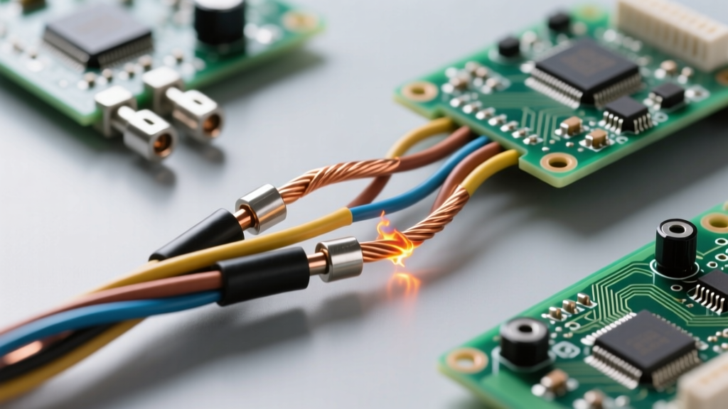
Aluminum exhibits a metallurgical property known as 'creep' or 'cold flow.' When placed under high mechanical pressure (like a lug screw), aluminum slowly deforms and flows away from the pressure point over time. Combined with its high coefficient of thermal expansion, an initially tight aluminum termination will inevitably loosen after months of load cycling. This loose connection increases contact resistance, generating intense localized heat that can ignite surrounding combustible materials.
To mitigate this, the Copper Development Association and NEC mandate specific practices: aluminum conductors must be cleaned with a wire brush, coated with an approved anti-oxidant compound (such as Noalox) to break down the oxide layer and prevent moisture ingress, and terminated using lugs specifically rated for AL/CU. Furthermore, periodic thermographic inspections are mandatory for aluminum feeders to detect loosening connections before they reach thermal runaway.
Insulation Breakdown: When the Conductor Survives but the Jacket Fails
A critical misconception in electrical safety is focusing on the melting point of the conductor metal. Copper melts at 1,984°F (1,085°C). However, the safety limit of a wire is dictated entirely by its insulation jacket, which fails at a fraction of that temperature.
Standard THHN/THWN-2 building wire is rated for 90°C (194°F) in dry locations and 75°C (167°F) in wet locations. If a conductor is overloaded, or if ambient temperatures inside an attic or near industrial piping exceed the design limits, the polymer insulation begins to cross-link, become brittle, and eventually crack. Once the dielectric barrier is compromised, arc tracking can occur. In high-voltage or high-frequency applications (such as VFD motor leads), partial discharge within microscopic voids in the insulation can erode the jacket from the inside out, leading to catastrophic phase-to-phase faults.
Safety Rule of Thumb: Always base your ampacity calculations on the lowest temperature rating of any connected component. Even if you use 90°C THHN wire, if the breaker lugs are only rated for 75°C, your conductor ampacity must be calculated using the 75°C column of NEC Table 310.16.
Termination Torque: The Most Overlooked Fire Hazard
Historically, electricians relied on the 'tug test' or wrist tension to secure conductor terminations. This subjective approach is a massive safety liability. Under-torqued connections result in high contact resistance and arcing. Over-torqued connections can strip threads, shear the conductor strands (reducing the effective cross-sectional area), or crush the metal, accelerating cold flow.
To address this, the NEC introduced Section 110.14(D), which strictly requires the use of calibrated torque tools to achieve the exact inch-pound (in-lbs) or Newton-meter (Nm) values specified by the equipment manufacturer.
Real-World Torque Specifications
- Standard 15A/20A Receptacles and Switches: Typically require 12 to 16 in-lbs. Over-tightening these small brass screws frequently strips the threads or crushes 12 AWG copper strands.
- 100A Molded Case Circuit Breaker (MCCB) Lugs: Often require 250 to 300 in-lbs. This requires a dedicated torque wrench or a calibrated torque screwdriver.
- Panelboard Neutral and Ground Bars: Often overlooked, but loose neutral connections cause voltage unbalance and can result in the neutral bar melting or arcing to the enclosure.
Always verify the manufacturer's torque data sheet. If the data is unavailable, refer to UL 486A-486B standard tables for default torque values based on screw size and thread pitch.
The Hidden Threat: Triplen Harmonics and Neutral Overloading
In modern commercial and industrial environments, the assumption that the neutral conductor carries zero current in a balanced three-phase system is a dangerous fallacy. The proliferation of non-linear loads—such as LED drivers, variable frequency drives (VFDs), computer power supplies, and EV chargers—generates massive amounts of harmonic distortion.
Specifically, 'triplen' harmonics (3rd, 9th, 15th, etc.) do not cancel out in the neutral. Instead, they add arithmetically. In a heavily loaded office building or data center, the neutral conductor can actually carry more current than the phase conductors. If the neutral was sized identically to the phase conductors (or worse, reduced in size as permitted by some older code cycles for specific feeders), it will overheat silently. Because the neutral is not protected by an overcurrent device (breaker), it can burn open or ignite surrounding insulation without ever tripping a protective device. For facilities with high non-linear loads, safety protocols dictate sizing the neutral conductor at 150% to 200% of the phase conductor ampacity, or utilizing K-rated transformers designed to handle harmonic heating.
Actionable Safety Checklist for Conductor Installation
Adhering to OSHA electrical safety standards and NEC requirements requires a systematic approach to conductor installation. Use this checklist before energizing any new circuit or feeder:
- Verify Derating Factors: Count all current-carrying conductors in the raceway. Apply NEC Table 310.15(C)(1) derating factors and adjust wire size accordingly.
- Check Ambient Temperature: If the conduit runs through a high-temperature area (e.g., above a dropped ceiling in a hot climate, or near steam pipes), apply the ambient temperature correction factors from Table 310.15(B)(1).
- Inspect Insulation Jacket: Look for micro-tears, abrasions, or whitish stress marks on the insulation caused by aggressive pulling. Use appropriate wire pulling lubricants rated for the specific insulation type.
- Prepare Aluminum Correctly: If using aluminum, wire-brush the strands immediately before termination, apply anti-oxidant paste, and use only AL/CU rated lugs.
- Torque to Spec: Use a calibrated torque screwdriver or wrench. Document the torque values on the panel schedule or commissioning report.
- Assess Harmonic Load: Evaluate the nature of the connected loads. If non-linear loads exceed 50% of the total capacity, upsize the neutral conductor and consider harmonic filtering.
Understanding the physical and chemical realities of conductors in electricity is the bedrock of electrical safety. By respecting thermal limits, material properties, and termination physics, you transition from simply 'making the circuit work' to engineering a resilient, fire-safe electrical infrastructure.