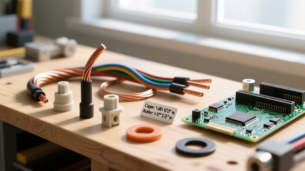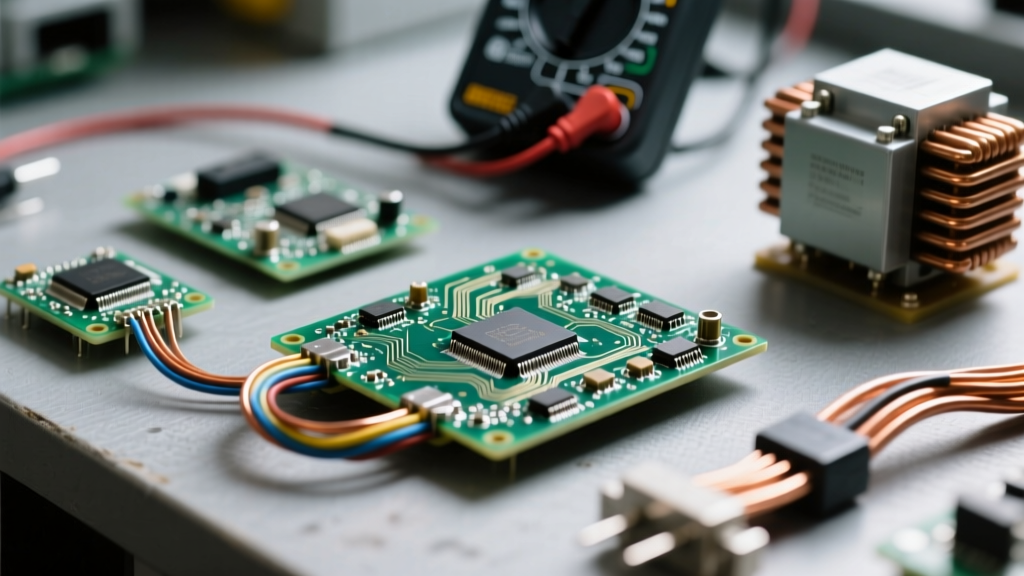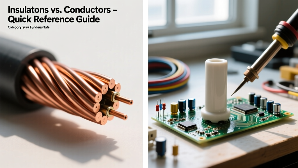

When designing circuits, sizing wire, or troubleshooting electrical faults, understanding the fundamental boundary between current flow and current restriction is critical. If you have ever asked what's the difference between insulators and conductors, the simplest answer lies in electron mobility. Conductors possess a vast sea of free electrons that easily migrate under an applied voltage, while insulators tightly bind their electrons to atomic nuclei, effectively blocking current flow. However, for electrical professionals and advanced DIYers, the real-world application goes far beyond basic definitions. This quick reference guide breaks down the atomic physics, material properties, and field-testing protocols that define these two essential categories.
The Atomic Divide: Band Theory in Practice
To truly grasp the difference, we must look at solid-state physics—specifically, band theory. In any material, electrons occupy specific energy levels grouped into 'bands'. The two most critical bands are the valence band (where electrons are bound to atoms) and the conduction band (where electrons are free to move and carry current).
- Conductors: The valence and conduction bands overlap. There is no 'band gap'. Even a tiny electromotive force (voltage) will push valence electrons into the conduction band, resulting in immediate current flow. Copper, aluminum, and silver are prime examples.
- Insulators: There is a massive energy gap (typically greater than 3 to 5 electron volts, or eV) between the valence and conduction bands. Under normal operating voltages, electrons cannot bridge this gap. Materials like PVC, Teflon (PTFE), and cross-linked polyethylene (XLPE) fall into this category.
- Semiconductors: The middle ground. They have a small band gap (around 1 eV). They act as insulators at absolute zero but become conductive when thermal energy or specific doping introduces charge carriers. Silicon and germanium are the standard bearers here.
Quick Reference: Conductor vs. Insulator Comparison Chart
The table below provides a high-level comparison of the defining metrics for common electrical materials at standard room temperature (20°C). Data sourced from standard resistivity tables and manufacturer dielectric specifications.
| Material | Classification | Electrical Resistivity (Ω·m) | Dielectric Strength (kV/mm) | Primary Electrical Application |
|---|---|---|---|---|
| Silver (Ag) | Conductor | 1.59 × 10⁻⁸ | N/A | High-end audio contacts, RF shielding |
| Copper (Cu) | Conductor | 1.68 × 10⁻⁸ | N/A | Standard AWG wiring, busbars, motor windings |
| Aluminum (Al) | Conductor | 2.82 × 10⁻⁸ | N/A | Overhead transmission, heavy feeder cables |
| PVC (Polyvinyl Chloride) | Insulator | ~1.0 × 10¹⁴ | ~40 kV/mm | THHN/THWN wire jacketing, general insulation |
| XLPE (Cross-linked PE) | Insulator | ~1.0 × 10¹⁶ | ~50 kV/mm | XHHW-2 wire, medium/high voltage underground cables |
| PTFE (Teflon) | Insulator | ~1.0 × 10¹⁸ | ~60 kV/mm | Aerospace wiring, high-temp thermocouple leads |
Source reference: For precise elemental resistivity metrics, consult the Georgia State University HyperPhysics resistivity tables.
Conductors in the Field: Resistivity and the Skin Effect
While silver is technically the most conductive elemental metal, copper is the undisputed king of practical electrical wiring due to its optimal balance of conductivity, tensile strength, and cost. When sizing conductors using circular mils or AWG charts, you are essentially calculating the cross-sectional area required to keep resistive heating (I²R losses) within safe limits.
The AC Skin Effect: In direct current (DC) circuits, electrons flow uniformly across the entire cross-section of a conductor. However, in alternating current (AC) circuits, changing magnetic fields force electrons toward the outer perimeter (the 'skin') of the wire. At 60Hz, this effect is negligible for standard residential AWG sizes but becomes a major factor in large industrial busbars and high-voltage transmission lines, which is why large AC conductors are often stranded or built as hollow tubes to save weight and material without sacrificing current capacity.
Insulators in the Field: Dielectric Breakdown and Thermal Limits
An insulator's primary job is to maintain the band gap under extreme electrical and thermal stress. However, no insulator is perfect. If the applied voltage exceeds a material's dielectric strength, the electric field will literally rip electrons from their atomic bonds, causing a catastrophic failure known as dielectric breakdown (an arc or short circuit).
Common Wire Insulation Types and Limits
- PVC (THHN/THWN): The standard for indoor residential and commercial wiring. Rated for 90°C in dry locations and 75°C in wet locations. It is flexible and cheap but emits toxic halogen gases when burned.
- XLPE (XHHW-2): Cross-linking the polyethylene polymer chain drastically improves thermal and chemical resistance. It maintains structural integrity up to 90°C (and can survive short-circuit spikes up to 250°C). It is the standard for outdoor, underground, and high-amperage feeder cables.
- PTFE (Teflon): As noted by Chemours (the creators of Teflon), fluoropolymer insulators offer near-infinite chemical resistance and can operate continuously at 260°C. It is heavily used in aerospace, military, and high-frequency data cables due to its exceptionally low dielectric constant, which minimizes signal loss.
Field Troubleshooting: When Insulators Become Conductors
Insulation degradation is a leading cause of electrical fires and equipment failure. Over time, heat, moisture, chemical exposure, and mechanical vibration cause microscopic cracks in the insulator. Moisture and carbon tracking then infiltrate these cracks, creating localized conductive paths. This leads to corona discharge and eventual phase-to-phase or phase-to-ground faults.
Step-by-Step Insulation Resistance (Megger) Testing
To proactively identify failing insulation before a short circuit occurs, electricians use a Megohmmeter (Megger). This device applies a high-voltage DC potential to measure leakage current through the insulator. According to Fluke's guidelines on insulation testing, follow this quick protocol:
- Isolate the Circuit: De-energize the equipment and disconnect all sensitive electronics (VFDs, PLCs) that could be destroyed by high-voltage DC.
- Select Test Voltage: Use 500V DC for standard 600V rated wire (like THHN). Use 1000V DC for 1000V rated cable.
- Apply and Read: Connect the positive lead to the conductor and the negative/ground lead to the equipment chassis or ground wire. Apply the voltage for 60 seconds.
- Evaluate: A healthy insulation system should read in the hundreds or thousands of Megohms (MΩ). If the reading drops below 1 MΩ (or falls below the manufacturer's minimum specification), the insulation is compromised and the wire must be replaced.
Quick Selection Matrix for DIY and Pro Wiring
Choosing the right conductor-insulator pairing depends entirely on the operating environment. Use this quick decision matrix for your next project:
- Standard Indoor Branch Circuits (15A/20A): Solid Copper Conductor + PVC/Nylon Insulation (THHN). Cheap, easy to strip, and perfectly suited for dry, climate-controlled environments.
- Outdoor/Underground Feeder Runs: Stranded Copper or Aluminum Conductor + XLPE Insulation (XHHW-2 or USE-2). Mandatory for wet locations and direct burial due to superior moisture and soil-chemical resistance.
- High-Temperature Zones (Ovens, Kilns, Engine Bays): Nickel-Plated Copper Conductor + PTFE or Fiberglass Braid Insulation. Standard PVC will melt and short out; you need materials rated for 200°C+.
- High-Frequency/RF Data Lines: Silver-Plated Copper Conductor + Foamed PTFE Insulator. Minimizes the skin effect resistance and reduces the dielectric constant to preserve high-speed signal integrity.
The Golden Rule of Wire Fundamentals: A conductor is only as good as its insulation. Sizing the copper for the correct ampacity prevents the wire from melting, but selecting the correct insulator for the environment prevents the circuit from arcing, shorting, and starting a fire. Always match the insulation type (THHN, XHHW, MTW) to the specific thermal and moisture constraints of your installation.