
When students or DIYers search for conductor define science, they are usually met with abstract textbook diagrams of electron seas and quantum band gaps. While understanding the atomic physics of conductivity is foundational, the real challenge for electrical professionals and advanced hobbyists lies in translating that quantum theory into safe, code-compliant, and reliable physical wiring systems. A conductor is not just a theoretical concept; it is a physical component subject to thermal expansion, galvanic corrosion, and mechanical stress.
In this comprehensive guide, we bridge the gap between solid-state physics and the workbench. We will explore how science defines a conductor at the atomic level, compare real-world metallic materials, and dive deep into the practical failure modes and sizing calculations that dictate modern electrical installations.
The Atomic Reality: How Science Defines a Conductor
To truly master wire sizing and material selection, you must first understand the atomic mechanics of conduction. In solid-state physics, a conductor is defined by its electronic band structure. Specifically, conductors possess a valence band (where electrons are bound to atoms) and a conduction band (where electrons are free to move and carry current) that overlap.
Because these bands overlap, there is no 'band gap' requiring external energy for electrons to jump into a conductive state. According to HyperPhysics at Georgia State University, this overlapping band structure creates a 'sea of free electrons' that can drift through the metal lattice when an electromotive force (voltage) is applied. However, this drift is not frictionless. As electrons move, they collide with the vibrating atoms of the metal lattice (phonons), generating heat. This atomic friction is what we measure macroscopically as electrical resistance.
From Theory to the Workbench: Material Selection
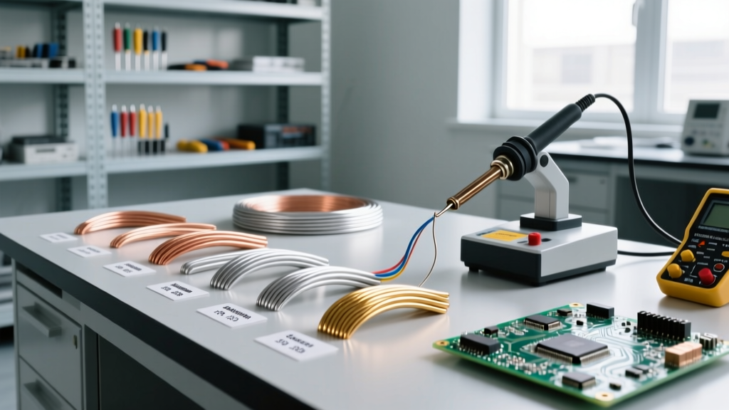
Not all conductors are created equal. The efficiency of a conductor is measured against the International Annealed Copper Standard (IACS), where pure annealed copper is set at exactly 100% conductivity. When selecting wire for a project, you are balancing conductivity, tensile strength, weight, and cost.
| Material | IACS Conductivity (%) | Resistivity (nΩ·m at 20°C) | Real-World Application |
|---|---|---|---|
| Silver | 105% | 15.9 | High-end audio contacts, aerospace relays, RF shielding. |
| Copper (Annealed) | 100% | 17.2 | Standard residential/commercial branch circuits, motor windings. |
| Gold | 70% | 24.4 | Corrosion-resistant PCB traces, low-voltage data connectors. |
| Aluminum (EC Grade) | 61% | 28.2 | Utility transmission lines, heavy feeder cables (SER/SEU). |
While silver is technically the superior conductor, copper remains the undisputed king of practical wiring due to its optimal balance of high conductivity, ductility, and resistance to oxidation. Aluminum, despite having only 61% of copper's conductivity, is widely used in heavy feeders and utility lines because it is significantly lighter and cheaper, requiring a larger gauge to carry the same ampacity.
Real-World Failure Mode: The Aluminum Oxidation and Creep Problem
Understanding the science of aluminum conductors is critical for avoiding catastrophic failures. Aluminum rapidly forms a tough, insulating oxide layer (aluminum oxide) when exposed to air. Unlike copper oxide, which is somewhat conductive and easily broken down by connection pressure, aluminum oxide is highly resistive. If you terminate an aluminum wire without properly abrading the surface and applying an antioxidant compound like Ideal Noalox, the connection will overheat.
Furthermore, aluminum suffers from 'thermal creep.' It expands and contracts at a different rate than brass or steel termination screws. Over hundreds of thermal cycles, the wire physically deforms and loosens under the screw head, increasing resistance and creating an arc-fault hazard. This is why the National Electrical Code (NEC) 110.14 strictly mandates the use of CO/ALR rated devices and specific torque values when terminating aluminum conductors.
Sizing Conductors for Practical Loads
Once you have selected your material, you must size it correctly. In the United States, wire sizing is governed by the American Wire Gauge (AWG) system for smaller wires, and circular mils (kcmil) for larger conductors.
The Math Behind Circular Mils
A circular mil is a unit of area equal to the area of a circle with a diameter of one mil (one-thousandth of an inch). The scientific reason we use circular mils instead of square millimeters in North American wire sizing is to simplify voltage drop calculations without using Pi. The cross-sectional area in circular mils is simply the diameter in mils, squared.
Expert Insight: Never size a long-run conductor based solely on NEC ampacity tables (NEC 310.15). Ampacity only tells you the current required to prevent the insulation from melting. You must also calculate voltage drop to ensure your equipment receives adequate operating voltage.
The standard voltage drop formula utilizing circular mils is:
VD = (2 × K × I × L) / CM
- VD: Voltage Drop
- K: Specific resistance of the material (approx. 12.9 for Copper, 21.2 for Aluminum)
- I: Current in Amperes
- L: One-way length of the circuit in feet
- CM: Cross-sectional area of the conductor in Circular Mils
For example, if you are running a 50-amp subpanel 150 feet away using copper wire, a standard #6 AWG (26,240 CM) might be legally ampable, but it will yield a voltage drop exceeding the recommended 3% limit for feeders. By applying the science of circular mils, you would calculate that upgrading to #4 AWG (41,740 CM) is necessary to maintain optimal system efficiency.
Insulators vs. Conductors: The Boundary of Safety
A conductor is only as safe as the insulator that bounds it. Science defines an insulator as a material with a massive band gap, preventing electron flow under normal conditions. However, in the real world, insulation is subject to dielectric breakdown.
When selecting wire, the insulation type (e.g., THHN, XHHW-2) dictates the thermal limits of the conductor. THHN (Thermoplastic High Heat-resistant Nylon-coated) is rated for 90°C in dry locations but is universally derated to 75°C for termination purposes due to the physical limitations of standard breakers and receptacles. XHHW-2 (Cross-linked Polyethylene) offers superior moisture resistance and a thinner profile, allowing more conductors to be pulled through a single conduit without violating NEC conduit fill capacity rules.
Troubleshooting Conductor Degradation in the Field
Even perfectly sized conductors degrade over time due to environmental factors, harmonic distortion, and mechanical vibration. As a domain expert, you must rely on empirical testing rather than visual inspection to verify conductor health.
- Infrared Thermography: Using a calibrated thermal camera (like a FLIR E8), scan all panel terminations under a minimum of 40% load. A temperature differential of more than 10°C between phases or a delta of 15°C above ambient indicates high-resistance connections caused by conductor creep or oxidation.
- Micro-Ohm Testing: For critical busbars and heavy feeders, use a digital low-resistance ohmmeter (DLRO). By injecting a known DC current (often 10A to 100A) and measuring the millivolt drop, you can detect internal conductor strand breakage or failing splices that a standard multimeter lacks the sensitivity to find.
- Harmonic Analysis: In commercial environments with heavy non-linear loads (VFDs, LED drivers, servers), the neutral conductor can carry more current than the phase conductors due to triplen harmonics. Use a true-RMS power quality analyzer to ensure your neutral conductor is scientifically sized to handle these additive harmonic currents, preventing catastrophic neutral overheating.
Conclusion
To define a conductor through the lens of science is to understand the quantum behavior of electrons, the thermodynamics of metal lattices, and the chemistry of oxidation. By applying these fundamental scientific principles to real-world wire sizing, material selection, and termination practices, you move beyond mere code compliance. You engineer electrical systems that are resilient, efficient, and fundamentally safe. Whether you are pulling 500 kcmil aluminum feeders for a commercial service or soldering 22 AWG copper for a microcontroller project, the physics remain exactly the same.