
When transitioning from residential DIY projects to commercial or industrial electrical work, understanding 3 phases electricity is the most critical hurdle to cross. While single-phase power relies on a single alternating current (AC) sine wave to deliver pulsing power, three-phase power utilizes three overlapping waves to create a continuous, high-density stream of energy. This fundamental shift in power delivery dictates everything from transformer topologies and wire sizing economics to motor efficiency and National Electrical Code (NEC) color standards.
The Physics Behind 3 Phases Electricity: The 120-Degree Shift
In a standard three-phase alternator, the stator contains three separate sets of windings. These windings are physically spaced 120 mechanical degrees apart around the rotor. As the magnetic rotor spins, it induces an AC voltage in each winding sequentially. The result is three distinct sine waves that are exactly 120 electrical degrees out of phase with one another.
Why does this matter for power delivery? In a single-phase 60Hz system, the voltage crosses zero 120 times per second. During those micro-seconds, instantaneous power drops to zero. In a balanced 3-phase system, when one phase crosses zero, the other two phases are still delivering significant voltage and current. The mathematical sum of the instantaneous power across all three phases is a constant, non-pulsing value. This is why three-phase motors run smoother, vibrate less, and require less copper to deliver the same horsepower as their single-phase counterparts.
Wye (Star) vs. Delta: Decoding Transformer Topologies
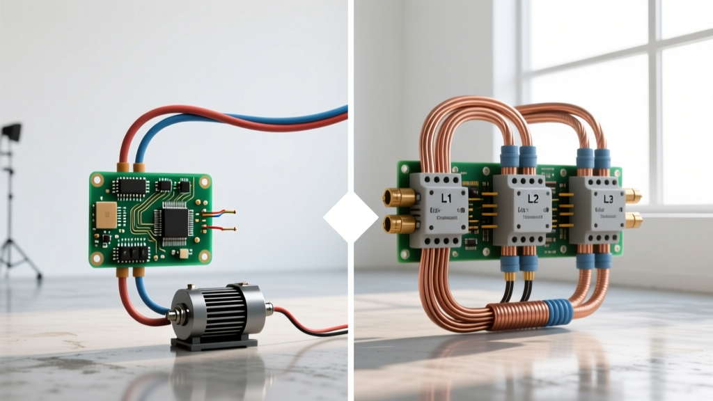
How 3 phases electricity is distributed depends heavily on the transformer configuration used by the utility or facility. There are two primary topologies:
The Wye (Star) Configuration
In a Wye configuration, one end of each of the three transformer windings is connected to a common neutral point. This setup provides two distinct voltages: a higher line-to-line voltage and a lower line-to-neutral voltage. The relationship is defined by the square root of 3 (approximately 1.732).
- 208Y/120V: Common in commercial buildings. Line-to-line is 208V (for HVAC and heavy machinery), while line-to-neutral is 120V (for standard outlets and lighting).
- 480Y/277V: Standard for large industrial facilities. 480V powers massive motors, while 277V is dedicated to high-bay LED lighting arrays, eliminating the need for step-down transformers on the lighting circuits.
Delta and the High-Leg Anomaly
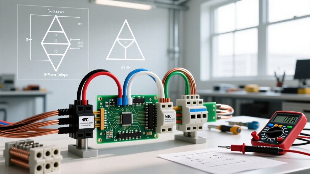
The Delta configuration connects the windings end-to-end in a triangle, meaning there is no natural neutral point. Line-to-line voltage is the only standard measurement. However, a specific variation known as the High-Leg Delta (or Wild-Leg Delta) is prevalent in older US industrial sites. By center-tapping one of the windings to ground, a 240V Delta system can provide 120V for lighting.
The catch? The phase opposite the center tap (the "high leg") will measure 208V to ground instead of 120V. Per NEC 110.15, this high-leg conductor must be identified by an Orange outer finish to prevent electricians from accidentally wiring a 120V appliance to a 208V phase, which would instantly destroy the equipment.
Wire Sizing Economics: Why Three Beats One
One of the most compelling reasons engineers specify 3 phases electricity for heavy loads is the dramatic reduction in wire gauge requirements. To understand the copper savings, we must look at the power formula for three-phase circuits:
I = P / (√3 × V × PF)
Where I = Current (Amps), P = Power (Watts), V = Line-to-Line Voltage, and PF = Power Factor.
Let us compare the wire sizing for a 20 kW (20,000W) resistive heating load (Power Factor = 1.0) using two different supply options:
Scenario A: 240V Single-Phase
- Current: 20,000 / 240 = 83.3 Amps
- Conductors Required: 2 current-carrying conductors plus ground.
- Wire Size (THHN Copper): Requires 3 AWG (rated for 100A at 75°C terminations).
- Total Copper Cross-Section: 2 × 52,620 circular mils = 105,240 cmil.
Scenario B: 480V 3-Phase
- Current: 20,000 / (1.732 × 480) = 24.0 Amps
- Conductors Required: 3 current-carrying conductors plus ground.
- Wire Size (THHN Copper): Requires 12 AWG (rated for 25A/30A depending on terminal ratings, though 10 AWG is often used for mechanical strength and voltage drop mitigation).
- Total Copper Cross-Section: 3 × 6,530 circular mils (for 12 AWG) = 19,590 cmil.
By utilizing 3 phases electricity at a higher voltage, the total copper mass required drops by over 80%. According to Eaton's power quality engineering guidelines, this reduction not only lowers material costs but significantly reduces conduit fill percentages, allowing for smaller, cheaper raceways and easier wire pulling.
NEC Color Code Standards for 3-Phase Systems
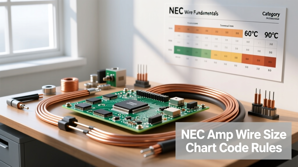
Misidentifying a phase in a three-phase panel can result in catastrophic equipment failure or lethal arc flashes. While the NEC does not strictly mandate specific colors for all ungrounded conductors universally, industry standards and specific local jurisdictions enforce the following color matrices to maintain consistency. Note that the high-leg delta requires special attention.
| System Type | Phase A | Phase B | Phase C | Neutral (Grounded) | Equipment Ground |
|---|---|---|---|---|---|
| 208Y/120V | Black | Red | Blue | White / Gray | Green / Bare |
| 480Y/277V | Brown | Orange | Yellow | Gray | Green / Bare |
| 240V Delta (High-Leg) | Black | Orange (High Leg) | Blue | White (if tapped) | Green / Bare |
Warning: Never assume panel labeling is correct. Always verify voltage line-to-line and line-to-ground with a CAT III or CAT IV multimeter before terminating conductors.
Troubleshooting Phase Imbalance in Industrial Motors
A perfectly balanced 3-phase system is a theoretical ideal. In reality, unevenly distributed single-phase loads (like 120V office circuits or 277V lighting) tapped off a three-phase transformer can cause voltage unbalance. For three-phase induction motors, phase imbalance is a silent killer.
According to the NEMA MG-1 Motors and Generators standard, a voltage unbalance as small as 1% can cause a 6% to 10% temperature rise in the motor windings. This occurs because the negative-sequence voltage created by the imbalance generates a reverse-rotating magnetic field, inducing high-frequency rotor currents that manifest as severe heat.
Calculating Voltage Unbalance
To determine if a motor needs to be derated, calculate the voltage unbalance using the NEMA formula:
- Measure the three line-to-line voltages (e.g., 480V, 472V, 465V).
- Calculate the average voltage: (480 + 472 + 465) / 3 = 472.3V.
- Find the maximum deviation from the average: |465 - 472.3| = 7.3V.
- Calculate percentage unbalance: (7.3 / 472.3) × 100 = 1.54%.
At 1.54% unbalance, the motor is operating outside ideal parameters. If the unbalance exceeds 5%, the motor must be severely derated or the facility must install active power factor correction and load-balancing equipment to prevent insulation breakdown and premature bearing failure.
Final Thoughts on 3-Phase Diagnostics
Mastering 3 phases electricity requires moving beyond basic continuity testing. Electricians and engineers must utilize phase-sequence meters to ensure motors rotate in the correct direction (A-B-C vs. A-C-B), and use power quality analyzers to measure harmonic distortion caused by Variable Frequency Drives (VFDs). By understanding the underlying physics, respecting the NEC color codes, and strictly monitoring phase balance, you can design and maintain three-phase systems that deliver maximum efficiency and operational longevity.