
Defining the Core: What Is a Grounding Electrode Conductor?
If you are designing a service entrance or troubleshooting a commercial electrical system, understanding the exact path of fault and surge currents is non-negotiable. So, what is a grounding electrode conductor (GEC)? In the simplest terms, the GEC is the physical wire that connects the electrical system's grounded conductor (usually the neutral bar at the service disconnect) to the grounding electrode system (ground rods, concrete-encased Ufer grounds, or metal underground water pipes).
Unlike conductors that carry normal operational load, the GEC sits idle during standard operation. Its primary jobs are to stabilize the system voltage to earth during normal operation and to provide a safe path to dissipate high-voltage transient events, such as lightning strikes or utility line surges. According to NFPA 70 (National Electrical Code) Article 250, the GEC is the vital bridge between your man-made electrical system and the earth.
GEC vs. EGC vs. Neutral: The Grounding Matrix
The most common point of confusion for apprentices and DIYers is mixing up the Grounding Electrode Conductor (GEC) with the Equipment Grounding Conductor (EGC) and the Grounded Conductor (Neutral). While they all ultimately tie back to the same busbar at the main service disconnect, their functions, sizing rules, and destinations are entirely different.
| Conductor Type | Primary Function | Destination | NEC Sizing Reference | Carries Load Current? |
|---|---|---|---|---|
| Grounding Electrode Conductor (GEC) | Dissipates lightning/surges; stabilizes voltage to earth. | Earth (Ground rods, Ufer, water pipe) | NEC Table 250.66 | No (Only during transient events) |
| Equipment Grounding Conductor (EGC) | Clears line-to-ground faults by tripping the breaker. | Appliance enclosures, metal conduit, panels | NEC Table 250.122 | No (Only during a fault) |
| Grounded Conductor (Neutral) | Provides the return path for unbalanced 120V load current. | Utility transformer, main service neutral bar | NEC Article 220 (Load Calc) | Yes (Continuous operational current) |
Information Gain Insight: Notice that the EGC is sized based on the overcurrent protective device (breaker size) to ensure it can handle massive fault current long enough to trip the breaker. The GEC, however, is sized based on the size of the service entrance conductors, because it must handle transient surges entering from the utility side, regardless of the downstream breaker sizes.
Material Showdown: Bare Copper vs. Aluminum GECs
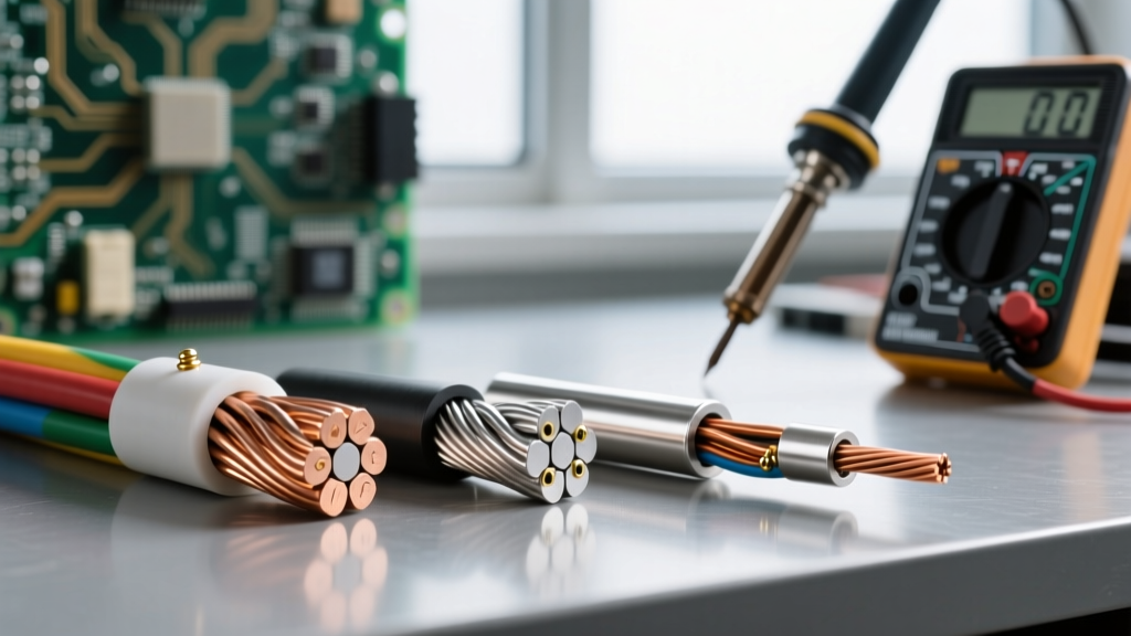
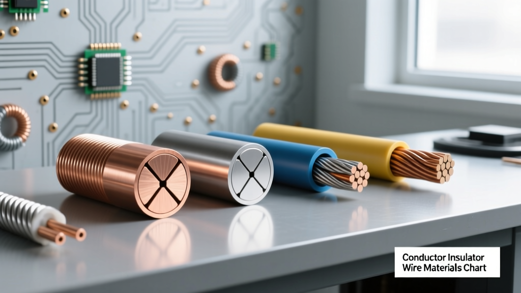
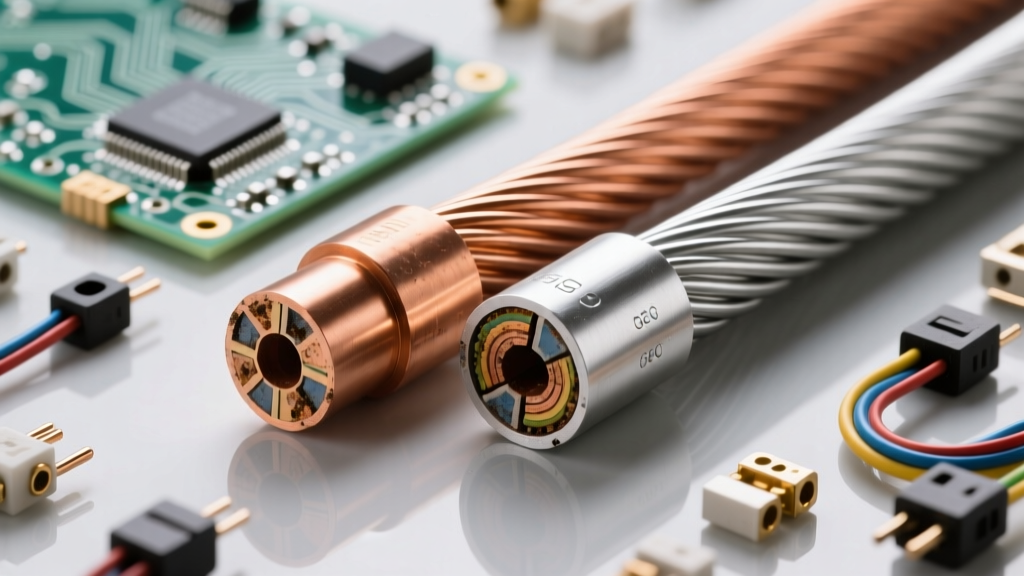
When selecting a GEC, the material choice directly impacts longevity, code compliance, and installation methodology. The Copper Development Association heavily advocates for copper in grounding applications due to its superior corrosion resistance, but aluminum is sometimes used in large commercial services to save on material costs.
Bare Copper (The Gold Standard)
- Pros: Highly resistant to soil and concrete corrosion. Can be directly buried or embedded in a Ufer ground without degradation. Excellent conductivity and thermal tolerance during lightning strikes.
- Cons: High material cost. Susceptible to theft on unsecured job sites.
- Best For: Residential services, direct-burial connections to ground rods, and concrete-encased electrodes.
Aluminum (The Budget Alternative)
- Pros: Significantly cheaper and lighter than copper for large feeders (e.g., 400A+ services).
- Cons: Highly susceptible to galvanic corrosion when in contact with concrete or soil. Requires anti-oxidant paste (like Noalox) at all termination points to prevent high-resistance connections.
- Code Restriction: The NEC strictly prohibits aluminum or copper-clad aluminum GECs from being terminated within 18 inches of the earth or in direct contact with concrete or soil.
- Best For: Interior runs in large commercial switchgear where the GEC terminates to a metallic water pipe above ground or a building steel column.
Sizing the GEC: NEC Table 250.66 Breakdown
Sizing a GEC is not a matter of guessing; it is a strict lookup exercise based on the circular mil area of your largest ungrounded service entrance conductor. Below is a practical comparison chart for common residential and light-commercial service sizes.
| Service Size (Amps) | Typical Copper Service Entrance Wire | Required Copper GEC Size (Full) | NEC 250.66 Max Size Limit (Rod/Pipe/Plate) | NEC 250.66 Max Size Limit (Ufer Ground) |
|---|---|---|---|---|
| 100A | #2 AWG | #8 AWG | #8 AWG | #8 AWG |
| 200A | 2/0 AWG | #4 AWG | #6 AWG | #4 AWG |
| 400A | 600 kcmil | 1/0 AWG | #6 AWG | #4 AWG |
| 800A | 1500 kcmil (Parallel) | 3/0 AWG | #6 AWG | #4 AWG |
Critical Code Nuance: Many electricians oversize the GEC unnecessarily. If your grounding electrode system consists solely of a ground rod, ground ring, or metal underground water pipe, NEC 250.66(A) and (B) state that the copper GEC never needs to be larger than #6 AWG (or #4 AWG for a Ufer ground), even if your service entrance conductors are massive 1500 kcmil cables. This is because the resistance of the earth itself bottlenecks the current transfer, making a 3/0 AWG wire to a single ground rod an exercise in wasted copper.
Real-World Installation Pitfalls and Code Violations
Even when sized correctly, improper installation of the GEC can render the entire grounding system useless. As highlighted by industry experts at EC&M Magazine, inspectors frequently flag the following field violations:
1. The Steel Conduit 'Choke' Effect
If you run a copper GEC through a steel conduit for physical protection, you must bond the steel conduit to the GEC at both ends using a grounding bushing. If you fail to do this, a heavy surge (like lightning) traveling down the GEC will induce a massive magnetic field in the surrounding steel pipe. This creates an inductive 'choke' effect, drastically increasing the impedance of the path and forcing the surge to flash over to nearby metallic systems, potentially destroying sensitive electronics.
2. Improper Clamps and Exothermic Welding
Using a standard 'acorn' clamp on a ground rod is acceptable for residential work, but in commercial or high-lightning areas, mechanical clamps can loosen over time due to thermal expansion and contraction. For mission-critical facilities (data centers, hospitals), specify Cadweld exothermic welding. This process uses a chemical reaction to melt copper alloy directly onto the ground rod, creating a molecular bond that will never loosen and offers superior surge-handling capabilities.
3. Bimetallic Corrosion at the Neutral Bar
When terminating an aluminum GEC to a copper neutral busbar, failing to use approved bimetallic lugs or anti-oxidant compounds will result in galvanic corrosion. Over 5 to 10 years, the connection degrades into a high-resistance white powder, effectively severing the system's tie to earth and leaving the facility vulnerable to utility-side surges.
Expert Verdict: Best Practices for Modern Services
Understanding what a grounding electrode conductor is goes far beyond memorizing a definition; it requires mastering the physics of transient surges and the chemistry of metallurgy. For standard 200A residential services, a continuous run of bare #4 AWG copper tied to a concrete-encased Ufer ground remains the most robust, code-compliant, and inspector-friendly method. For commercial services exceeding 400A, leverage the NEC sizing limits to avoid overspending on massive copper runs, and always mandate exothermic welding or heavy-duty cast-bronze clamps (like the Ilsco DBT series) for earth terminations. By treating the GEC as a critical surge-defense component rather than an afterthought, you ensure the longevity and safety of the entire electrical ecosystem.