
The Core Mechanics of Electricity Alternating Current
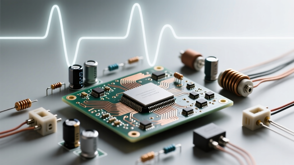
Unlike direct current (DC), which flows uniformly in a single direction, electricity alternating current (AC) periodically reverses its direction of flow. This oscillation is not a random fluctuation but a precisely engineered sine wave generated by electromagnetic induction. When a conductor rotates through a magnetic field within an alternator, the induced voltage swings from zero to a positive peak, back through zero, to a negative peak, and finally returns to zero, completing one full cycle.
The primary advantage of AC over DC lies in its ability to be easily stepped up to high voltages for long-distance transmission via transformers, drastically reducing $I^2R$ (heat) losses, and then stepped down for safe residential and commercial use. Understanding the precise behavior of AC is critical for electrical engineers, DIY enthusiasts, and electricians, as it directly dictates wire sizing, breaker selection, and power quality troubleshooting.
AC Waveform Anatomy: Peak, Peak-to-Peak, and RMS
To properly size conductors and select protective devices, you must understand how AC voltage and current are measured. The constantly changing nature of a sine wave means that a single 'voltage' number requires context. Here are the fundamental measurement metrics:
- Peak Voltage ($V_p$): The maximum absolute value reached by the waveform from the zero-crossing line.
- Peak-to-Peak Voltage ($V_{pp}$): The total voltage difference between the maximum positive peak and the maximum negative peak ($V_{pp} = 2 \times V_p$).
- Root Mean Square (RMS): The most critical metric for electrical work. RMS represents the equivalent DC voltage that would produce the exact same amount of heat in a resistive load. When we refer to '120V AC', we are exclusively referring to the RMS value.
For a perfect sine wave, the mathematical relationship is fixed: $V_{rms} = V_p \times 0.707$. As noted in Fluke's guide on True-RMS measurements, relying on RMS is the only way to accurately calculate real power dissipation and thermal loading on electrical wiring.
Table 1: Standard AC Voltage Measurement Reference Chart
| Nominal RMS Voltage | Peak Voltage ($V_p$) | Peak-to-Peak ($V_{pp}$) | Common Application |
|---|---|---|---|
| 120V | 169.7V | 339.4V | North American Standard Receptacles |
| 208V | 294.1V | 588.2V | Commercial 3-Phase Wye Systems |
| 240V | 339.4V | 678.8V | Residential Dryers, Ovens, HVAC |
| 277V | 391.7V | 783.4V | Commercial Lighting (Phase-to-Neutral) |
| 480V | 678.8V | 1357.6V | Industrial Motors and Heavy Machinery |
Single-Phase vs. Three-Phase Power Systems
Electricity alternating current is distributed in either single-phase or three-phase configurations, and the choice drastically impacts conductor sizing and system architecture.
Single-Phase AC utilizes one alternating voltage waveform. In North America, residential split-phase systems use a center-tapped transformer secondary to provide both 120V (phase-to-neutral) and 240V (phase-to-phase). Because power delivery pulsates, dropping to zero twice per cycle, single-phase systems are less efficient for heavy inductive loads like large motors.
Three-Phase AC utilizes three distinct waveforms, each offset by exactly 120 electrical degrees. This phase shift ensures that the total power delivered to a balanced load remains constant, never dropping to zero. According to the U.S. Energy Information Administration, three-phase power is the backbone of the commercial and industrial grid because it allows for smaller, more efficient conductors to transmit the same amount of power compared to single-phase systems.
The Skin Effect: How AC Alters Wire Sizing Rules
One of the most profound differences between DC and AC wiring is the skin effect. When direct current flows through a wire, the electron density is uniform across the entire cross-section of the conductor. However, alternating current generates a changing magnetic field inside the conductor, which induces eddy currents that oppose the flow of electrons in the center. Consequently, AC current is forced toward the outer 'skin' of the wire.
The depth at which current density falls to 37% of its surface value is known as the skin depth ($\delta$). For copper at a standard 60Hz utility frequency, the skin depth is approximately 8.5 mm.
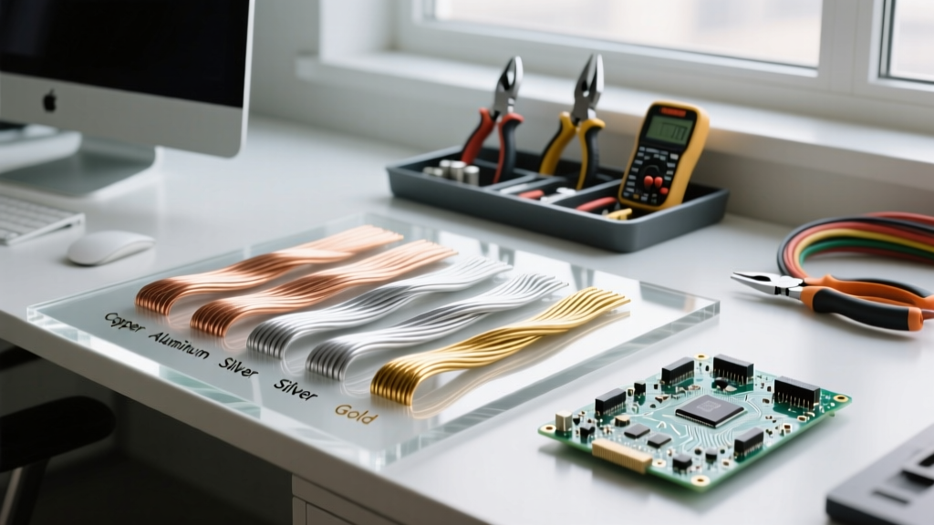
Expert Wire Sizing Insight: Because standard residential wires (like 12 AWG or 10 AWG) have diameters well under 8.5 mm, the skin effect is virtually negligible at 60Hz. However, for massive utility busbars or high-frequency applications—such as the pulse-width modulated (PWM) output cables from Variable Frequency Drives (VFDs) operating at 2kHz to 10kHz—the skin depth shrinks to fractions of a millimeter. In these scenarios, standard solid wire becomes highly inefficient, and engineers must specify Litz wire (individually insulated, braided strands) or specialized symmetrical VFD cables to prevent severe overheating and insulation failure.
For a deeper dive into the physics of AC impedance and skin effect, All About Circuits provides excellent mathematical models detailing how proximity effect and skin effect compound in tightly bundled AC cable trays.
Frequency Standards and Global Grid Variations
The frequency of electricity alternating current—measured in Hertz (Hz)—dictates the speed of AC motors and the design of magnetic components like transformers. The world is largely divided into two frequency camps: 60Hz (primarily the Americas, parts of Asia) and 50Hz (Europe, most of Africa and Asia).
Table 2: Global AC Frequency and Voltage Reference
| Region | Frequency | Standard Residential Voltage | Impact on Equipment |
|---|---|---|---|
| North America | 60 Hz | 120V / 240V (Split-Phase) | Motors run faster; transformers can be physically smaller. |
| European Union | 50 Hz | 230V (Single-Phase) | Higher transmission voltage allows thinner residential wires. |
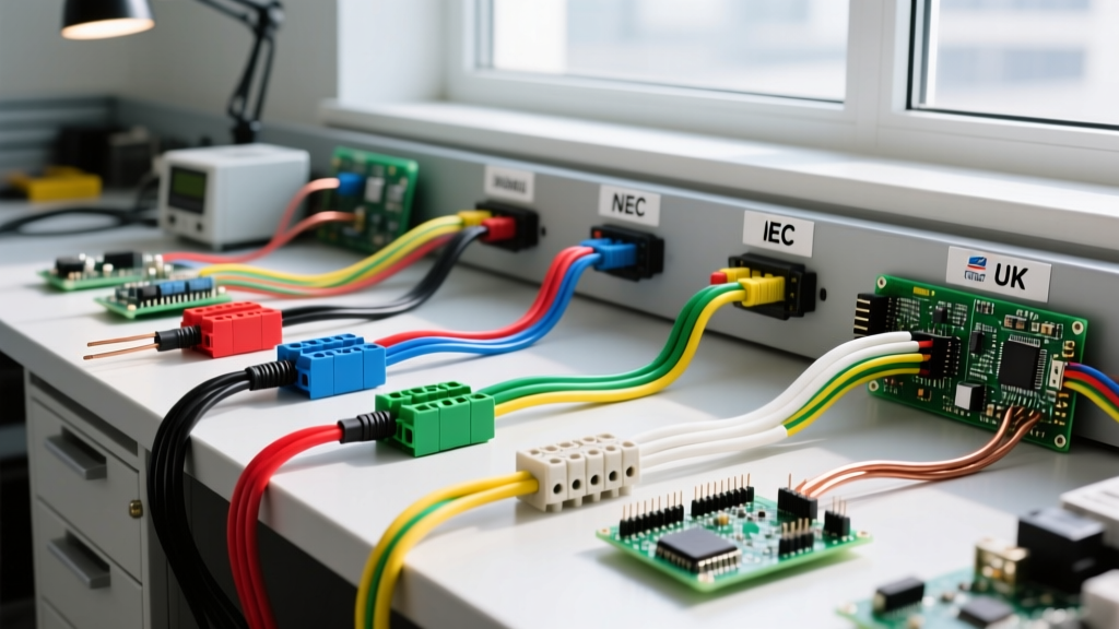
| United Kingdom | 50 Hz | 230V (Single-Phase) | Strict ring-main circuit topology dictates unique wiring rules. |
| Japan | 50 Hz / 60 Hz | 100V (Single-Phase) | Eastern grid is 50Hz, Western grid is 60Hz; requires frequency converters. |
Troubleshooting Common AC Power Anomalies
In modern electrical systems, the pure sine wave of electricity alternating current is rarely perfect. Non-linear loads—such as LED drivers, computer power supplies, and VFDs—draw current in abrupt, high-amplitude pulses rather than a smooth continuous wave. This introduces harmonics into the AC system.
When troubleshooting AC circuits, be aware of the following anomalies:
- Harmonic Distortion (THD): High 3rd-order harmonics do not cancel out in the neutral conductor of a three-phase wye system. Instead, they add up, potentially causing the neutral wire to carry more current than the phase wires and overheat. Always size neutral conductors to 200% capacity in environments heavy with switching power supplies.
- Voltage Sags and Swells: Brief drops or spikes in RMS voltage caused by heavy motor starting or grid switching. These can cause contactors to drop out or sensitive microcontrollers to reset.
- Poor Power Factor (PF): Inductive loads cause the current waveform to lag behind the voltage waveform. While the real power (Watts) might be low, the apparent power (VA) forces the wiring to carry higher current. Wire ampacity must always be calculated using the apparent current, adjusted for the load's power factor, to prevent conductor overheating.
By mastering the behavior of electricity alternating current—from the mathematical certainty of RMS calculations to the physical realities of the skin effect and harmonic distortion—you ensure that your wiring designs are not only code-compliant but thermally robust and optimized for long-term reliability.