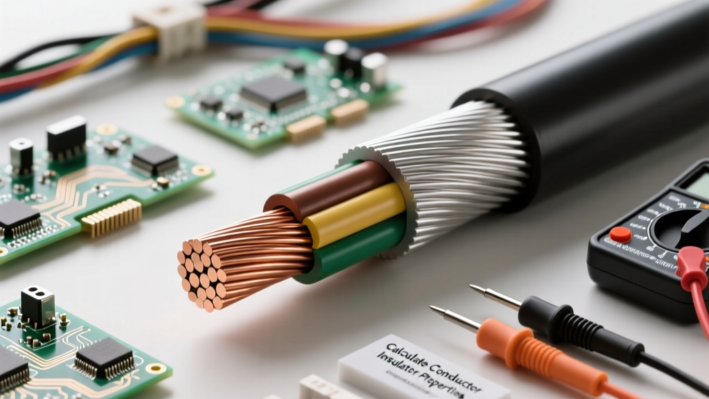

Beyond Definitions: The Mathematics of Electrical Materials
When an electrical engineer or advanced DIYer asks, "what is a conductor and what is an insulator," the standard textbook answer is straightforward: a conductor permits the free flow of electrons, while an insulator restricts it. However, in the realm of wire sizing, circuit design, and electrical fundamentals, qualitative definitions are insufficient. To build safe, efficient, and code-compliant systems, we must define these materials mathematically.
This calculation tutorial bridges the gap between atomic theory and practical engineering. We will explore the exact formulas used to calculate conductor resistance under thermal stress, determine insulator dielectric breakdown margins, and model the parasitic capacitance that occurs when these two materials interact in a real-world cable assembly.
The Physics of Flow: Defining Conductors Mathematically
A conductor is defined by its low electrical resistivity ($\rho$), a property dictated by the availability of free valence electrons in its atomic lattice. Copper and aluminum are the industry standards, but their performance fluctuates based on temperature and physical dimensions. To understand what a conductor is in a practical sense, we must calculate its exact resistance in a given circuit.
Calculating Conductor Resistance Under Thermal Load
The baseline resistance of a wire is calculated using the formula:
$R = \rho \frac{L}{A}$
- $R$ = Resistance in Ohms ($\Omega$)
- $\rho$ = Resistivity of the material (e.g., $1.68 \times 10^{-8} \, \Omega\cdot m$ for annealed copper at 20°C, per HyperPhysics)
- $L$ = Length of the conductor in meters
- $A$ = Cross-sectional area in square meters
However, conductors heat up under load. The resistivity of copper increases linearly with temperature according to the temperature coefficient ($\alpha$), which is $0.00393 / ^\circ C$ for copper. The adjusted resistivity formula is:
$\rho_T = \rho_{20} [1 + \alpha(T - 20)]$
Calculation Example: Let us calculate the resistance of a 100-foot (30.48m) run of 12 AWG solid copper wire operating at its maximum rated temperature of 75°C.
- Find Area: 12 AWG has a cross-sectional area of 6,530 circular mils, which converts to $3.31 \times 10^{-6} \, m^2$.
- Adjust Resistivity: $\rho_{75} = 1.68 \times 10^{-8} [1 + 0.00393(75 - 20)] = 1.68 \times 10^{-8} [1.216] = 2.04 \times 10^{-8} \, \Omega\cdot m$.
- Calculate Resistance: $R = \frac{2.04 \times 10^{-8} \times 30.48}{3.31 \times 10^{-6}} = 0.188 \, \Omega$.
While a 20°C calculation would yield $0.155 \, \Omega$, the thermal reality of a loaded conductor increases resistance by over 21%. This mathematical reality is why voltage drop calculations must always use the hot resistivity value to prevent undersized wire selection.
The Physics of Blocking: Defining Insulators Mathematically
If a conductor is defined by electron mobility, an insulator is defined by its band gap—the energy required to free an electron from its atom. In wire sizing, we evaluate insulators (like PVC, XLPE, or Teflon) using dielectric strength, which is the maximum electric field a material can withstand before it breaks down and becomes conductive.
Dielectric Breakdown and Safety Margin Calculations
Dielectric strength ($E_{max}$) is measured in kilovolts per millimeter (kV/mm). The breakdown voltage ($V_{bd}$) of a specific insulation layer is calculated as:
$V_{bd} = E_{max} \times d$
Where $d$ is the insulation thickness in millimeters.
Calculation Example: Standard THHN wire uses a PVC insulation jacket. According to material data sheets referenced by Britannica and wire manufacturers, rigid PVC has a conservative dielectric strength of roughly 15 kV/mm. For a standard 12 AWG THHN wire, the PVC insulation thickness is approximately 0.38 mm (0.015 inches).
$V_{bd} = 15 \, \text{kV/mm} \times 0.38 \, \text{mm} = 5,700 \, \text{Volts}$.
Even though THHN is rated for 600V circuits, the mathematical breakdown voltage is 5,700V. This yields a Dielectric Safety Factor of 9.5. This massive mathematical margin is necessary because insulators degrade over time due to thermal cycling, mechanical abrasion, and partial discharge.
Comparative Material Properties Matrix
To truly grasp what is a conductor and what is an insulator, compare their fundamental physical constants side-by-side. The table below highlights why specific materials are chosen for wire manufacturing.
| Material | Role | Resistivity ($\Omega\cdot m$ at 20°C) | Dielectric Strength (kV/mm) | Relative Permittivity ($\epsilon_r$) |
|---|---|---|---|---|
| Silver | Conductor | $1.59 \times 10^{-8}$ | N/A | N/A |
| Copper (Annealed) | Conductor | $1.68 \times 10^{-8}$ | N/A | N/A |
| Aluminum (1350) | Conductor | $2.82 \times 10^{-8}$ | N/A | N/A |
| PVC (Polyvinyl Chloride) | Insulator | $> 10^{14}$ | 10 - 40 | 3.0 - 4.0 |
| XLPE (Cross-linked PE) | Insulator | $> 10^{16}$ | 20 - 50 | 2.3 |
| PTFE (Teflon) | Insulator | $> 10^{18}$ | 60 - 100 | 2.1 |
Advanced Interaction: Calculating Parasitic Capacitance
When you combine a conductor and an insulator into a coaxial or multi-conductor cable, you inadvertently create a capacitor. In long AC runs or high-frequency data lines, this parasitic capacitance can cause significant leakage currents and signal degradation. The Anixter Wire & Cable FAQ notes that ignoring cable capacitance is a leading cause of VFD (Variable Frequency Drive) motor failures.
The capacitance ($C$) per meter of a single insulated conductor (acting as a coaxial cylinder with the ground plane) is calculated using:
$C = \frac{2 \pi \epsilon_0 \epsilon_r}{\ln(r_2 / r_1)}$
- $\epsilon_0$ = Permittivity of free space ($8.854 \times 10^{-12} \, \text{F/m}$)
- $\epsilon_r$ = Relative permittivity (dielectric constant) of the insulator
- $r_1$ = Radius of the conductor
- $r_2$ = Outer radius of the insulation
Calculation Example: Using our 12 AWG copper wire ($r_1 = 1.025 \, \text{mm}$) with 0.38mm PVC insulation ($r_2 = 1.405 \, \text{mm}$), and assuming a PVC $\epsilon_r$ of 3.5:
$C = \frac{2 \pi (8.854 \times 10^{-12}) (3.5)}{\ln(1.405 / 1.025)} = \frac{1.947 \times 10^{-10}}{0.3148} = 6.18 \times 10^{-10} \, \text{F/m}$, or 618 pF/m.
In a 500-meter industrial run, this results in $309 \, \text{nF}$ of parasitic capacitance. At high switching frequencies, this capacitance draws substantial reactive current ($I_c = V \times 2\pi f C$), proving that the insulator's chemical composition directly dictates the AC performance of the conductor.
Real-World Failure Modes: When Math Meets Reality
Understanding what is a conductor and what is an insulator mathematically allows us to predict failure modes that basic visual inspections miss.
1. The Skin Effect in AC Conductors
In alternating current (AC) circuits, electrons do not use the entire cross-section of the conductor. They are pushed to the outer edge due to self-induced eddy currents. The depth of this active layer is the skin depth ($\delta$):
$\delta = \sqrt{\frac{2\rho}{\omega \mu}}$
At 60 Hz, the skin depth in copper is approximately 8.5 mm. If you are sizing a solid copper conductor larger than 17 mm in diameter for 60 Hz AC power, the mathematical center of the conductor carries almost zero current. This is why high-amperage busbars and large gauge wires are either stranded, hollow, or constructed of multiple parallel runs to maximize surface area.
2. Partial Discharge in Insulators
Insulators do not always fail catastrophically. Microscopic voids within XLPE or PVC insulation can ionize under high voltage gradients, leading to partial discharge (PD). Over years of thermal cycling, these micro-arcs chemically erode the insulator from the inside out, creating conductive carbonized tracks (electrical trees) that eventually bridge the gap between the conductor and the ground plane, resulting in a dead short.
Engineering Takeaway: The distinction between a conductor and an insulator is not a permanent binary state; it is a mathematical threshold governed by temperature, voltage gradient, and frequency. Proper wire sizing requires calculating the exact thermal and dielectric limits of both materials to ensure the system remains safely within its operational boundaries.