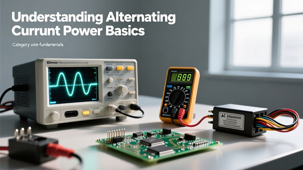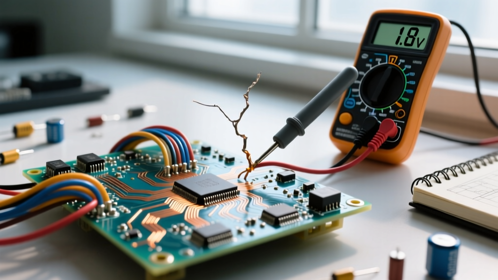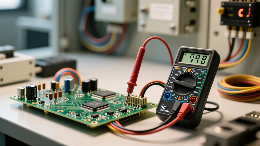

Direct current power is the lifeblood of modern electronics, microcontrollers, and off-grid solar arrays. Unlike alternating current (AC), which periodically reverses direction and crosses zero volts, direct current (DC) maintains a constant, unidirectional flow of electrical charge. While this steady state is essential for digital logic and battery storage, it introduces unique, often hidden failure modes. Because DC never crosses zero, electrical arcs sustained at disconnecting contacts are longer and hotter, leading to accelerated pitting. Furthermore, the continuous unidirectional flow promotes electromigration and galvanic corrosion at dissimilar metal junctions. For DIYers and field technicians, troubleshooting direct current power requires a fundamentally different approach than diagnosing standard mains AC wiring.
The Anatomy of Direct Current Power Failures
When a DC circuit fails to operate correctly, the root cause almost always falls into one of three categories: excessive voltage drop, polarity reversal, or high-frequency ripple. Understanding the physics behind these failures is the first step toward effective troubleshooting.
Voltage Drop vs. Source Sag
A common mistake in DC troubleshooting is misidentifying the source of low voltage. Source sag occurs when the power supply itself cannot maintain its rated voltage under load, often due to thermal throttling, inadequate current capacity, or failing internal filter capacitors. Voltage drop, on the other hand, occurs in the wiring between the source and the load. According to All About Circuits, Ohm's Law dictates that any resistance in the conductor will result in a proportional loss of voltage. In low-voltage DC systems (like 12V or 24V), even a 1.5V drop represents a massive 12.5% loss, which is enough to cause microcontrollers like the ESP32 to brown-out and reset continuously.
Polarity Reversal and Component Destruction
Unlike AC devices, DC components are strictly polarity-sensitive. Reversing the positive and negative terminals can be catastrophic. Electrolytic capacitors subjected to reverse voltage will rapidly heat, vent, and potentially explode due to the breakdown of their internal dielectric oxide layer. Semiconductor junctions, such as those found in linear regulators (e.g., the LM7805), will suffer avalanche breakdown if the reverse voltage exceeds their Peak Inverse Voltage (PIV) rating. Troubleshooting a dead board often begins with checking for shorted protection diodes or melted polarity-protection MOSFETs.
Diagnostic Toolkit for DC Circuits
To accurately diagnose direct current power anomalies, standard continuity testers are insufficient. You need tools that can capture dynamic electrical behavior.
- True-RMS Digital Multimeter (DMM): A high-quality meter like the Fluke 87V is essential. While True-RMS is primarily an AC feature, a high-end DMM provides the millivolt DC resolution needed to measure shunt resistors and trace voltage drops across PCB tracks.
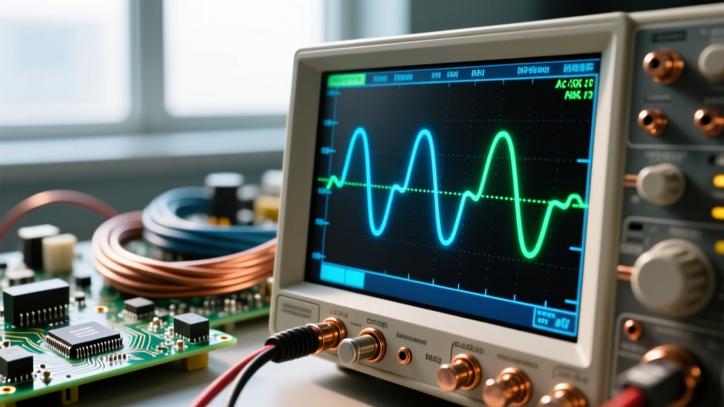
- Digital Oscilloscope: A scope (such as the Rigol DS1054Z) is mandatory for detecting AC ripple superimposed on a DC rail. Switching power supplies (SMPS) can introduce high-frequency noise that a standard multimeter will completely miss.
- Thermal Imaging Camera: High-resistance connections in DC circuits generate localized heat. A thermal camera like the FLIR C5 allows you to instantly spot oxidized crimp connectors or overloaded traces on a circuit board without touching them.
Step-by-Step Troubleshooting Protocol
When confronted with a malfunctioning DC system, follow this sequential protocol to isolate the fault without risking further damage to sensitive logic boards.
Phase 1: Open-Circuit Voltage Verification
Disconnect the load entirely and measure the voltage directly at the power supply terminals. If you are troubleshooting a 12V lead-acid battery system, a healthy, fully charged battery should read between 12.6V and 12.8V. If the open-circuit voltage is correct, the power source is likely healthy, and the issue lies downstream. If the voltage is low, the fault is isolated to the power supply or battery chemistry.
Phase 2: Loaded Voltage Drop Mapping
Reconnect the load and power the system. Measure the voltage at the source, then measure it again at the exact point where the load connects. As noted by the Fluke Corporation, the difference between these two readings is your total circuit voltage drop. If the drop exceeds 3% of the nominal system voltage, your wire gauge is too small, or your connectors are degraded. Remember to measure the drop on both the positive supply wire and the negative ground return wire; ground-side voltage drops are notoriously common and frequently overlooked.
Phase 3: Ripple and Noise Analysis
If the DC voltage is correct and the wiring is adequate, but the microcontroller is still behaving erratically, suspect power rail noise. Connect your oscilloscope probe to the DC rail, set the coupling to 'AC', and adjust the vertical scale to 50mV/div. A clean linear regulator will show a flat line. A failing switching buck converter may reveal 200mV to 500mV of high-frequency ripple. This AC noise can couple into analog-to-digital converter (ADC) pins, causing erratic sensor readings.
Wire Sizing and Connector Degradation in DC Systems
Wire sizing for direct current power is far less forgiving than for AC mains. Because DC systems operate at lower voltages, the same wattage requires significantly higher current, making I²R (power loss) heating a major concern. Furthermore, DC current causes continuous electromigration, meaning electrons physically push metal ions in one direction, which can eventually degrade crimps and terminal blocks over years of service.
Below is a reference table for copper wire voltage drops in a standard 12V DC system drawing 10 Amps over a 20-foot total loop (10 feet out, 10 feet back).
| Wire Gauge (AWG) | Resistance (Ω/1000ft) | Voltage Drop (10A, 20ft loop) | Power Loss (Watts) | Suitability for 12V/10A |
|---|---|---|---|---|
| 18 AWG | 6.385 | 1.27 V | 12.7 W | Fail (10.5% Drop) |
| 16 AWG | 4.016 | 0.80 V | 8.0 W | Poor (6.6% Drop) |
| 14 AWG | 2.525 | 0.50 V | 5.0 W | Acceptable (4.1% Drop) |
| 12 AWG | 1.588 | 0.31 V | 3.1 W | Excellent (2.5% Drop) |
| 10 AWG | 0.998 | 0.20 V | 2.0 W | Optimal (1.6% Drop) |
Pro-Tip: Never rely solely on the wire's insulation thickness to judge its gauge. Many cheap, imported DC power cables feature thick PVC jackets hiding incredibly thin 22 AWG stranded copper inside, leading to severe voltage drops and potential fire hazards.
Ground Loops and the DC Return Path
In complex DIY projects combining motors, relays, and sensitive sensors, the DC return path (ground) can become a major source of interference. A ground loop occurs when there are multiple paths to the common ground, creating a loop that acts as an antenna for magnetic fields or allows high-current return spikes to modulate the ground reference of sensitive components.
For example, if a 12V DC motor and a 5V Arduino share the same thin ground wire back to the battery, the motor's startup surge (which can be 5x its running current) will momentarily raise the voltage of the ground wire. To the Arduino, this ground shift looks like a sudden drop in supply voltage, triggering a brown-out reset. The troubleshooting fix is to implement a star grounding topology, where every load and sensor has its own dedicated ground wire running directly back to a single, massive central grounding busbar, as recommended in SparkFun's engineering tutorials.
Summary Checklist for Field Technicians
Before tearing apart a direct current power system, run through this rapid diagnostic checklist:
- Verify Source Voltage: Measure at the battery or supply terminals under zero load.
- Measure Loaded Voltage: Check the voltage at the load while the system is actively drawing current.
- Calculate the Drop: Ensure the total drop (positive + negative legs) is under 3% of nominal voltage.
- Inspect for Galvanic Corrosion: Look for green/white crust on copper-to-brass or copper-to-aluminum DC connections.
- Check for AC Ripple: Use an oscilloscope to ensure switching regulators are not injecting noise into the DC rail.
- Audit Ground Topology: Ensure high-current loads do not share ground return wires with low-voltage logic circuits.
By treating direct current power not just as a simple battery-to-load connection, but as a complex system susceptible to resistance, noise, and electrochemical degradation, you can systematically eliminate faults and build highly reliable electronic systems.