
The Atomic Reality: Why Materials Behave Differently in the Field
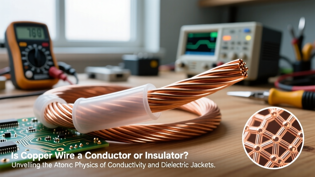
When evaluating insulators vs conductors for real-world electrical installations, the distinction goes far beyond basic textbook definitions. At the atomic level, conductors possess a 'sea of electrons' in their valence band that are loosely bound and free to migrate when an electromotive force (voltage) is applied. Insulators, conversely, have tightly bound electrons with a massive energy bandgap, preventing electron flow under normal conditions. However, in practical DIY and professional electrical work, the absolute nature of these categories blurs. No insulator is perfect; every dielectric material has a breakdown voltage, and every conductor has inherent resistance. Understanding how these materials behave under thermal stress, mechanical strain, and environmental exposure is what separates a safe, long-lasting installation from a catastrophic fire hazard.
Conductor Selection: Moving Beyond Basic Copper
While copper is the undisputed king of residential and commercial wiring, real-world applications demand a nuanced understanding of conductor metallurgy and geometry. The standard for electrical copper is Electrolytic Tough Pitch (ETP) C11000, which defines 100% of the International Annealed Copper Standard (IACS) for conductivity. However, when sourcing wire, you must be vigilant about material substitutions.
The CCA Trap and Aluminum Realities
Copper Clad Aluminum (CCA) wire has flooded the DIY market, often sold deceptively as pure copper. CCA features an aluminum core with a thin copper electroplated exterior. Because aluminum has only about 61% of the conductivity of copper (by volume), a 12 AWG CCA wire will overheat if subjected to the same 20-amp continuous load as a 12 AWG solid copper wire. CCA is also highly susceptible to galvanic corrosion when terminated with standard brass or copper lugs, leading to high-resistance hot spots.
Legitimate aluminum wiring, however, has its place. According to the NFPA 70 National Electrical Code (NEC), specifically Article 310.14, aluminum branch-circuit conductors must be an AA-8000 series alloy. This specific alloying process adds iron and other trace elements to eliminate the historical issues of aluminum 'creep' and thermal expansion that caused widespread connection failures in the 1970s. When using AA-8000 aluminum, you must upsizing the gauge (e.g., using 2 AWG aluminum to replace 4 AWG copper) and apply anti-oxidant compound (like Noalox) at terminations.
Stranding Classes: Flexibility vs. Termination
Conductors are not just solid or stranded; they follow specific ASTM stranding classes. Class B (compressed strand) is standard for THHN building wire, offering a good balance of flexibility and terminal compatibility. Class K (highly flexible) is used in welding cables and robotics, featuring hundreds of micro-strands. While Class K reduces conductor fatigue from continuous vibration, its high surface area makes it prone to oxidation and requires specialized ferrules or set-screw lugs to prevent individual strands from escaping the terminal block and causing short circuits.
Insulation Jackets: Dielectric Strength and Thermal Limits
When comparing insulators vs conductors, the insulator's primary job is to contain the electrical field and prevent phase-to-phase or phase-to-ground faults. The dielectric strength of an insulator is measured in kilovolts per millimeter (kV/mm). While air has a dielectric strength of roughly 3 kV/mm, solid insulators range wildly based on their chemical composition.
THHN vs. XHHW-2: The Nylon Factor
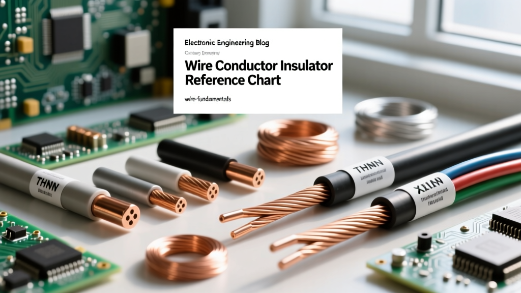
THHN (Thermoplastic High Heat-resistant Nylon-coated) is the most common wire found in residential conduit. It features a PVC base insulation rated for 90°C in dry locations, wrapped in a thin Nylon jacket. The Nylon provides excellent mechanical abrasion resistance, making it easy to pull through crowded conduits. However, Nylon is hygroscopic—it absorbs moisture. If THHN is used in a continuously wet location (like an underground conduit or a dairy farm), the nylon degrades, and the PVC underneath is exposed to water, eventually leading to insulation breakdown.
For wet locations, XHHW-2 (Cross-Linked Polyethylene) is the superior choice. XLPE insulation is chemically cross-linked, creating a thermoset matrix that does not melt under high heat and is entirely impervious to moisture wicking. It lacks the nylon jacket, making it slightly thicker and harder to pull, but its longevity in harsh environments far outpaces THHN.
High-Temperature and Aerospace Applications
In extreme environments, such as kiln wiring or aerospace applications, standard thermoplastics will melt or off-gas toxic fumes. PTFE (Polytetrafluoroethylene, or Teflon) is utilized for its incredible thermal stability (up to 260°C) and chemical inertness. Silicone rubber is another premier insulator; while its dielectric strength is lower than PTFE and its mechanical tear resistance is poor, it remains highly flexible at sub-zero temperatures, making it ideal for outdoor robotic actuators and cold-storage facility wiring.
Material Comparison Matrix for Field Electricians
The following table provides a practical reference for selecting the right conductor and insulator pairing based on real-world environmental constraints.
| Material Type | Conductivity / Dielectric Metric | Max Continuous Temp | Primary Failure Mode | Best Real-World Application |
|---|---|---|---|---|
| ETP Copper (Solid) | 100% IACS | N/A (Depends on Jacket) | Mechanical fatigue (snapping) | Standard residential branch circuits |
| AA-8000 Aluminum | ~61% IACS (by volume) | N/A (Depends on Jacket) | Thermal creep at lugs | Heavy feeders, service entrances |
| PVC (w/ Nylon - THHN) | ~15 - 20 kV/mm | 90°C (Dry) / 75°C (Wet) | Nylon moisture wicking | Indoor commercial conduit pulls |
| XLPE (XHHW-2) | ~25 - 30 kV/mm | 90°C (Dry & Wet) | Mechanical abrasion during pull | Underground conduits, wet locations |
| PTFE (Teflon) | ~60 kV/mm | 260°C | Cold flow under compression | Kilns, aerospace, high-frequency RF |
Real-World Failure Modes and Diagnostic Testing
Understanding the theoretical differences between insulators vs conductors is useless if you cannot diagnose degradation in the field. Insulation does not usually fail instantly; it degrades over time due to thermal cycling, corona discharge, and chemical exposure.
Insulation Resistance (IR) and Megger Testing
To test the integrity of an insulator without destroying it, professionals use a Megohmmeter, such as the Fluke 1587 FC Insulation Multimeter. By injecting a high DC voltage (typically 500V or 1000V for low-voltage systems) into the conductor, you measure the micro-current that leaks through the insulator to the ground or shield. A healthy, newly installed 600V THHN circuit should read well over 100 Megohms. If the reading drops below 1 Megohm, the insulation is compromised, often due to invisible micro-tears sustained during the wire pulling process or long-term thermal degradation.
The Polarization Index (PI) Test
For large motors and heavy industrial feeders, a single IR test is insufficient because surface moisture can skew the results. The Polarization Index test measures the insulation resistance at 1 minute and divides it by the resistance at 10 minutes. As the DC voltage is applied, the molecules within the insulator physically align (polarize), creating an opposing electric field that reduces the leakage current over time. A PI ratio of less than 2.0 indicates brittle, contaminated, or moisture-logged insulation that requires immediate replacement, even if the 1-minute absolute resistance seemed acceptable.
Corona and Partial Discharge
In medium and high-voltage applications (above 2kV), the electric field around a conductor can exceed the dielectric strength of the surrounding air, causing 'corona discharge.' This manifests as a faint hissing sound and a bluish glow, producing ozone gas that rapidly eats away at rubber and PVC insulators. To combat this, high-voltage cables use semi-conducting shields to smooth the electric field gradient, ensuring the stress is distributed evenly across the insulator rather than concentrating at microscopic air voids.
Best Practices for DIY and Pro Installations
When designing or repairing a circuit, always match the insulator's thermal and environmental rating to the worst-case scenario of the installation environment, not just the ambient room temperature. A wire bundled tightly with six other current-carrying conductors in a sealed wall cavity will experience severe thermal buildup. According to NEMA Wire and Cable Standards and NEC ampacity derating tables, you must reduce the allowable current capacity of the conductor to prevent the insulator from melting or prematurely aging. Finally, never strip a conductor further back than necessary; exposed copper is an uninsulated antenna for oxidation and accidental ground faults. The gap between the insulation jacket and the terminal lug should be no more than 1/16th of an inch, ensuring the dielectric barrier remains intact right up to the point of mechanical connection.