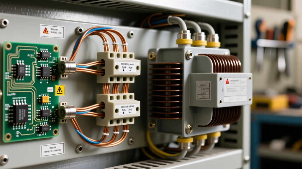

Proper transformer wiring is the backbone of reliable industrial control circuits and commercial power distribution. Whether you are stepping down 480V three-phase to 120V single-phase for a motor control center or configuring a 24V isolation transformer for HVAC controls, misinterpreting a schematic can lead to catastrophic equipment failure or severe electrical hazards. This reference guide breaks down the exact wiring configurations, multi-tap jumper settings, and NEC-compliant overcurrent protection strategies required for modern step-down and control transformers.
Anatomy of a Step-Down Transformer Schematic
Before connecting a single wire, you must understand the standard nomenclature used in transformer wiring diagrams. The National Electrical Manufacturers Association (NEMA) and IEEE standards dictate specific labeling for primary and secondary windings to ensure phase consistency and polarity alignment.
Primary vs. Secondary Winding Identification
The primary winding (the input side) is universally labeled with H-designations (H1, H2, H3, H4). The secondary winding (the output side) uses X-designations (X1, X2, X3, X4). In a standard single-phase control transformer, H1 and H2 represent the two ends of the primary coil, while X1 and X2 represent the secondary. When dealing with dual-voltage primaries (e.g., 240x480V), you will encounter H1 through H4, which require specific series or parallel jumper configurations depending on your supply voltage.
CRITICAL SAFETY NOTE: Never assume the physical placement of terminals matches the schematic. Always verify the nameplate diagram. On many Square D and Siemens control transformers, H1 and H3 are on one side, while H2 and H4 are on the opposite side. Cross-wiring these jumpers will create a dead short across the primary winding, resulting in an immediate arc flash and destroyed equipment.
Multi-Tap Primary Configurations (240V vs. 480V)
Dual-voltage transformers utilize two identical primary coils. The way you wire the interconnecting jumpers dictates whether the transformer operates in series (for higher voltage) or parallel (for lower voltage). Below is the definitive jumper matrix for standard single-phase control transformers.
| Supply Voltage | Connection Type | Jumper Configuration | Line Connections |
|---|---|---|---|
| 480V AC | Series | H2 to H3 | L1 to H1, L2 to H4 |
| 240V AC | Parallel | H1 to H3, H2 to H4 | L1 to H1/H3, L2 to H2/H4 |
| 208V AC | Parallel (with tap) | H1 to H3, H2 to H4 | L1 to H1/H3, L2 to H2/H4 (Use 208V tap if available) |
Control Circuit Transformer Wiring Diagram (480V to 120V)
Let us examine a real-world scenario: wiring a 150VA control transformer (such as the Schneider Electric 90-T150F3) to step down 480V to 120V for a PLC control panel. The wiring diagram must account not only for the physical connections but also for the inrush current and NEC Article 450 overcurrent protection requirements. For deeper schematic verification, referencing Schneider Electric Technical Support documentation is highly recommended for specific model variations.
Sizing Overcurrent Protection Devices (OCPD)
Transformer inrush current can be 10 to 40 times the nominal full-load current for the first few cycles. If you wire standard fast-acting fuses, they will blow every time the panel is energized. You must use time-delay fuses (like Class RK5) on the primary side.
For our 150VA transformer at 480V, the primary full-load current (FLC) is calculated as:
Primary FLC = VA / Voltage = 150 / 480 = 0.312 Amps
According to NEC Article 450.3(B), for a primary current of less than 2 amps, the OCPD can be rated up to 500% of the primary FLC to accommodate inrush. Therefore, 0.312A x 5 = 1.56A. The next standard fuse size is 1.75A or 2A. On the secondary side (120V), the FLC is 1.25A. NEC 450.3(B) dictates that if the secondary current is less than 2 amps, you must use a secondary fuse rated at no more than 167% of the secondary FLC (1.25 x 1.67 = 2.08A), meaning a standard 2A slow-blow fuse is required on the X1 leg.
Polarity Testing and Additive/Subtractive Wiring
When wiring transformers in parallel or configuring them for specific isolation requirements, understanding polarity is non-negotiable. Transformers are manufactured with either additive or subtractive polarity, which dictates how the voltage vectors sum together.
The 9V Battery Flash Test
If the nameplate is obscured and you need to verify the H1 and X1 polarity marks before wiring, you can perform a simple inductive kick test:
- Connect a sensitive analog DC voltmeter (or galvanometer) across the secondary terminals X1 and X2. Connect the positive lead to X1.
- Momentarily touch a 9V DC battery across the primary terminals H1 and H2, with the positive terminal to H1.
- Observe the meter needle upon connection. If the needle kicks in the positive (upward) direction, the transformer has subtractive polarity (H1 and X1 are physically on the same side and share the same instantaneous polarity).
- If the needle kicks negative (downward), it has additive polarity.
This test is crucial when wiring instrument transformers (CTs and PTs) for metering, as reversed polarity will cause power meters to read backward or trip reverse-power relays.
Troubleshooting Common Transformer Wiring Faults
Even with a correct schematic, field conditions introduce variables that can mimic transformer failure. Here is a diagnostic framework for common wiring anomalies:
- Symptom: Primary breaker trips instantly upon energization.
Diagnosis: This is rarely a bad transformer. It is almost always incorrect primary jumper wiring (e.g., wiring H1-H2 and H3-H4 in series instead of H2-H3), creating a shorted turn. Alternatively, the OCPD is not a time-delay type and is tripping on standard magnetizing inrush current. - Symptom: Secondary voltage is present but drops severely under load.
Diagnosis: Check the VA rating against the actual load. A 50VA transformer powering a 75VA contactor coil and indicator lights will suffer massive voltage sag due to winding impedance. Measure the secondary voltage with a true-RMS multimeter while the contactor is pulling in; if it drops below 85% of nominal, the contactor will chatter and burn out its coil. - Symptom: 60V to 90V phantom reading on secondary when primary is energized but secondary is open.
Diagnosis: Capacitive coupling between the primary and secondary windings. This is normal in ungrounded isolation transformers. To eliminate this phantom voltage and stabilize the secondary reference to earth, you must bond one leg of the secondary (usually X2) to the equipment grounding conductor, as mandated by OSHA electrical safety standards and NEC 250.20 for separately derived systems.
Grounding Separately Derived Systems (SDS)
A critical mistake in transformer wiring is failing to recognize that the secondary of a step-down transformer is a separately derived system (SDS). The neutral (X2) is not inherently grounded just because the primary neutral was grounded. You must install a system bonding jumper between the secondary neutral (X2) and the ground bus bar of the new panel. Furthermore, a grounding electrode conductor (GEC) must be run from this secondary neutral to the nearest effectively grounded building steel or grounding electrode. Failure to establish this SDS ground reference leaves the secondary floating, allowing transient voltage spikes from lightning or switching surges to puncture the transformer insulation and destroy downstream PLCs. Always size the system bonding jumper according to NEC Table 250.102(C)(1) based on the secondary conductor size to ensure fault currents can safely clear the secondary OCPD.