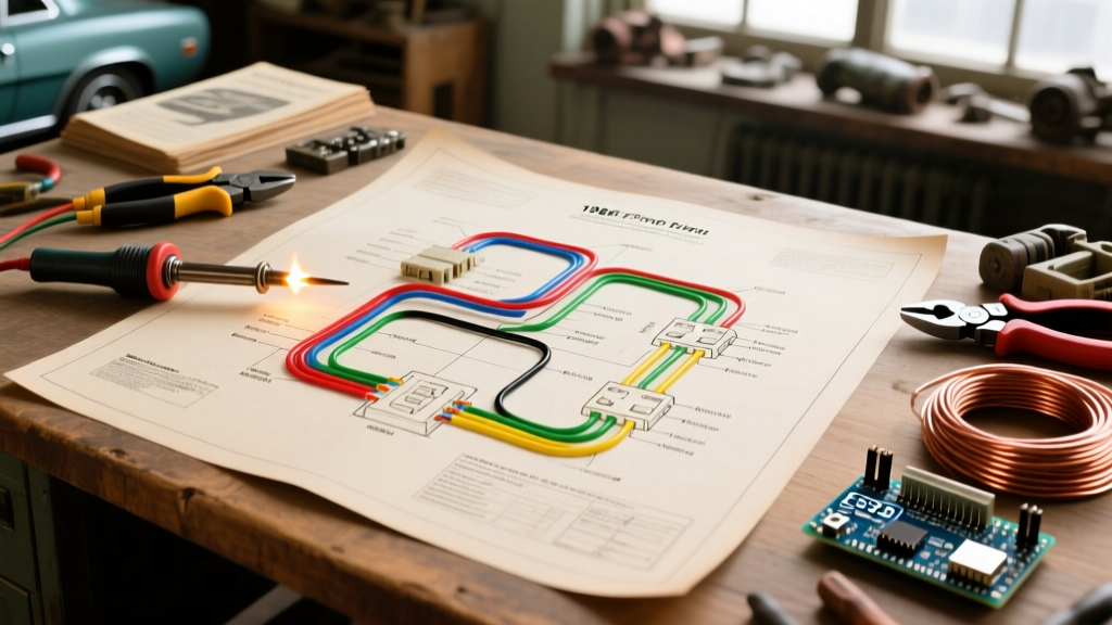
The Bottom Line: A single phase wire diagram is a schematic that maps the routing of one alternating current voltage waveform—typically split into two 120V legs and a shared neutral in North American homes—to supply both standard outlets and high-power appliances. This diagram dictates exactly what changes in your physical installation: whether you pull three wires (hot, neutral, ground) for 120V or four wires (two hots, neutral, ground) for 240V, which directly determines your breaker pole count, wire gauge, and insulation color codes. Beginners frequently confuse "single phase" with "three phase" commercial power, or fail to realize that North American residential "single phase" is technically a "split-phase" system derived from a center-tapped transformer.
The Core Anatomy of a Residential Split-Phase System
To read or draw a single phase wire diagram for a US or Canadian home, you must first understand the utility transformer sitting on the pole outside. The utility delivers a single phase of AC power to a center-tapped step-down transformer. This transformer outputs 240V across its two outer taps (Leg 1 and Leg 2) and 120V from either outer tap to the center tap (the Neutral).
According to the National Electrical Code (NEC) Article 100, this is defined as a single-phase, 3-wire system. Here is how the conductors map out on your diagram:
- Leg 1 (L1): Black wire, 120V relative to neutral, 240V relative to L2.
- Leg 2 (L2): Red wire, 120V relative to neutral, 240V relative to L1. (Note: L1 and L2 are 180 degrees out of phase with each other).
- Neutral (N): White or gray wire. This is a current-carrying conductor that handles the unbalanced return current between L1 and L2.
- Equipment Ground (EGC): Bare copper or green wire. This carries zero current under normal operation and exists solely to trip the breaker during a ground fault.
The most common confusion on the workbench is mixing up the neutral and the ground. On your diagram, the neutral must always route to the neutral bus bar (which is bonded to ground only at the main service disconnect), while the bare ground routes to the ground bus bar. In a subpanel, these two bars must remain strictly isolated.
Where You Meet This in Practice
You will encounter single phase wire diagrams in three primary residential scenarios, each demanding a different wiring topology:
1. Standard 120V Branch Circuits
This is your standard lighting and receptacle circuit. The diagram shows a single-pole breaker connecting to one hot leg (Black), a shared neutral (White), and a ground (Bare). The voltage is measured from L1 to N (or L2 to N), yielding 120V nominal.
2. Pure 240V Resistive Loads
Think of older electric baseboard heaters or simple water heaters. The diagram routes L1 and L2 directly to the appliance. Because the load bridges the full 240V potential, the current flows back and forth between the two hot legs. A neutral wire is not required on the diagram for these specific loads, though a ground wire is always mandatory.
3. 120/240V Mixed Appliances (Dryers, Ranges, EV Chargers)
Modern appliances often need 240V for the heavy lifting (heating elements, compressor motors) and 120V for control boards, timers, and interior lights. Your diagram must show a 4-wire setup: L1, L2, Neutral, and Ground. The neutral provides the 120V return path for the low-power electronics. The NEC strictly requires 4-wire diagrams for new installations of these appliances; 3-wire setups are only grandfathered in existing, unmodified older homes.
Worked Numeric Example: Sizing a 240V Baseboard Heater Circuit
Let’s translate a theoretical single phase wire diagram into physical materials. Suppose you are wiring a new 3000W, 240V electric baseboard heater in a finished basement. Here is the exact math and code-compliant part selection.
NEC Continuous Load Rule: Under NEC 210.20(A), any load expected to run for 3 hours or more (like a baseboard heater in winter) is considered a "continuous load." You must multiply the calculated current by 1.25 to size the breaker and wire.
Step 1: Calculate Base Current
Using Ohm’s Law (I = P / V):
3000W / 240V = 12.5 Amps.
Step 2: Apply the Continuous Load Multiplier
12.5A × 1.25 = 15.625 Amps.
Step 3: Select the Breaker
NEC 240.6 lists standard breaker sizes (15, 20, 25, 30, etc.). Since 15.625A exceeds a 15A breaker, you must step up to the next standard size: a 20A double-pole breaker.
Step 4: Select the Wire Gauge
Per NEC 310.16, 14 AWG copper is rated for 15A, and 12 AWG copper is rated for 20A (using the 60°C column for standard residential terminations). Therefore, you must pull 12 AWG wire.
Step 5: Finalize the Diagram Materials
Your diagram calls for 12/2 NM-B (Romex) cable. The black wire goes to L1, the white wire must be re-identified with black or red electrical tape at both ends to serve as L2, and the bare wire is the ground. No neutral is required at the heater itself.
Decision Tree: Selecting Wire and Breakers for Your Diagram
Use this decision matrix to finalize the component picks for your single phase wire diagram. This table assumes standard copper conductors in a residential environment with an ambient temperature of 30°C (86°F).
| Load Type / Scenario | Voltage | Max Continuous Current | Breaker Pick (Poles / Amps) | Wire Pick (NM-B Cable) |
|---|---|---|---|---|
| Standard Receptacles (Living Room) | 120V | 14A | 1-Pole, 15A or 20A | 14/2 or 12/2 NM-B |
| Kitchen Small Appliance Circuit | 120V | 16A | 1-Pole, 20A | 12/2 NM-B |
| 3000W Baseboard Heater | 240V | 15.6A (Calc) | 2-Pole, 20A | 12/2 NM-B (White re-marked) |
| Electric Dryer (Modern) | 120/240V | 24A | 2-Pole, 30A | 10/3 NM-B (with Ground) |
| EV Level 2 Charger (48A output) | 240V | 48A | 2-Pole, 60A | 6/2 NM-B or 6 AWG THHN in conduit |
Critical Wiring Mistakes to Avoid
When executing a single phase diagram, a few specific errors lead to immediate code violations or severe fire hazards. The Electrical Safety Foundation International (ESFI) frequently cites these in residential fire investigations:
The Multi-Wire Branch Circuit (MWBC) Neutral Trap
An MWBC uses a 3-wire cable (Black, Red, White) to supply two separate 120V circuits from opposite legs (L1 and L2) while sharing a single neutral. Think of the neutral like a highway merge lane: if cars (current) from L1 and L2 arrive at the exact same time (in phase), the lane overloads. Because L1 and L2 are 180 degrees out of phase, their return currents cancel each other out in the neutral, keeping it safe. The fatal mistake: If an electrician accidentally connects both the black and red wires to the same leg (e.g., both on L1) in the panel, the cancellation fails, and the shared neutral will carry the combined sum of both circuits, melting the insulation and starting a fire inside the wall. Always use a 2-pole breaker or a handle-tied pair of 1-pole breakers for MWBCs to ensure they land on opposite legs and disconnect simultaneously.
Bootleg Grounds on 3-Prong Outlets
When upgrading older 2-wire (ungrounded) circuits, some DIYers install a 3-prong receptacle and jumper the neutral terminal to the ground screw to trick a receptacle tester. This is a lethal violation. If the neutral wire ever breaks upstream, the metal casing of any plugged-in appliance will become energized at 120V. If your diagram lacks a ground wire, you must either pull new cable or install a GFCI receptacle marked "No Equipment Ground" per NEC 406.4(D).
FAQ: Single Phase Diagram Clarifications
Can I use a single-phase wire diagram for a 3-phase motor?
No. A 3-phase motor requires three distinct hot legs (L1, L2, L3) spaced 120 degrees apart, typically yielding 208V or 480V. A residential single-phase panel cannot natively supply this. You would need a Variable Frequency Drive (VFD) or a rotary phase converter to generate the third leg from a single-phase source.
Why do European single-phase diagrams look different?
In the UK and EU, the utility delivers true single-phase power at 230V nominal. Their diagrams feature one hot (Brown), one neutral (Blue), and one ground (Green/Yellow). There is no center-tapped split-phase system, meaning they do not use double-pole breakers for standard household appliances; a single 230V hot leg handles everything from phone chargers to electric ovens.
What is the default recommendation for general home wiring?
If you are designing a single phase wire diagram for standard 120V general-use receptacle circuits and are unsure of the exact future load, default to 12 AWG copper wire on 20A single-pole breakers. While 14 AWG on 15A breakers is code-compliant and cheaper, the 12 AWG/20A baseline drastically reduces voltage drop on long runs, keeps conductors cooler under load, and accommodates high-draw devices like shop vacuums or space heaters without nuisance tripping.