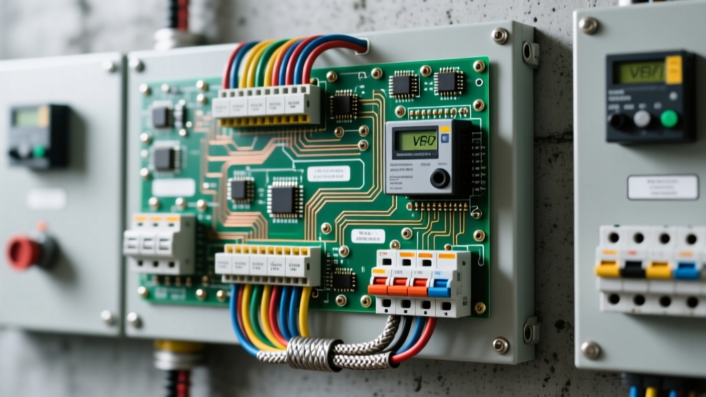

The Anatomy of a Panel-Mounted Potentiometer Circuit
When integrating a manual speed control interface into an industrial Motor Control Center (MCC) or Variable Frequency Drive (VFD) panel, the pot wiring diagram is deceptively complex. In consumer electronics, a potentiometer (pot) simply alters voltage. In an industrial control panel, a 10k Ohm linear pot acts as a critical Human-Machine Interface (HMI) that dictates motor torque, tensioning, and process regulation. A flawed wiring schematic doesn't just result in poor performance; it introduces ground loops, electromagnetic interference (EMI), and catastrophic motor hunting.
This guide bridges the gap between low-voltage analog signaling and high-voltage panel architecture. We will dissect the proper integration of a panel-mounted pot, focusing on control circuit breaker sizing, shield termination, and NFPA 79 compliance.
Control Circuit Breaker Sizing & Protection
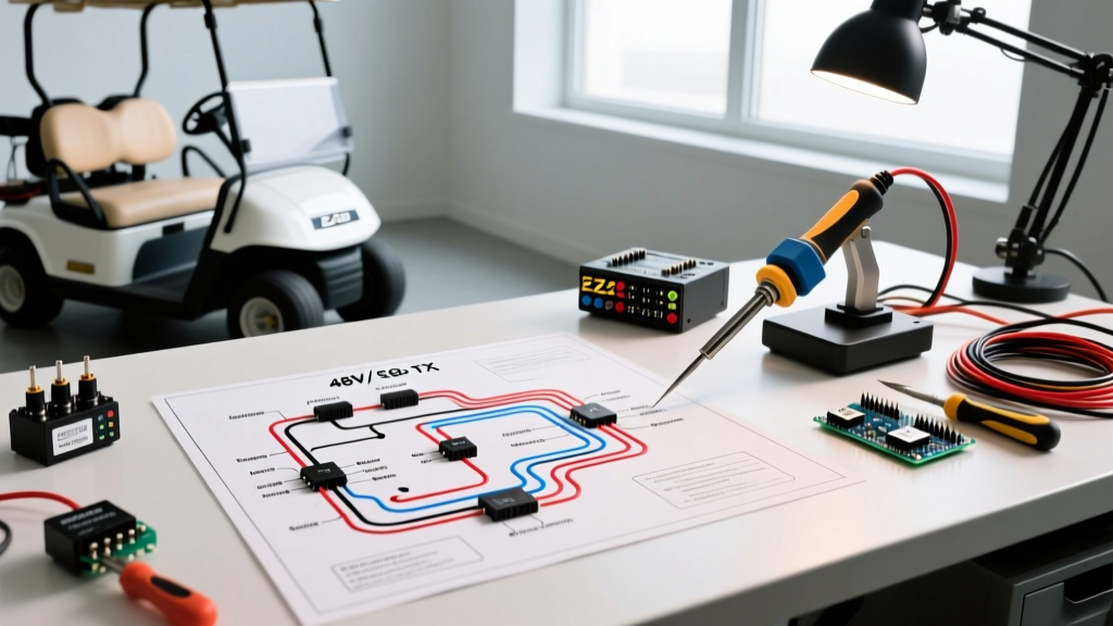
Before routing analog signals, we must establish a protected control voltage architecture. While many VFDs provide an internal +10VDC reference, best practices in panel design dictate using an isolated, external 10VDC or 24VDC power supply (such as a Phoenix Contact QUINT4) to prevent drive-induced noise from corrupting the analog reference.
According to UL 508A guidelines for Industrial Control Panels, control circuits must be protected against short circuits. For a 24VDC control circuit powering external analog transmitters and potentiometer networks, a 1-Pole, 2A to 4A Miniature Circuit Breaker (MCB) with a Curve C trip characteristic is standard. If the pot is wired directly to the VFD's internal +10V terminal, the drive's internal current-limiting circuitry acts as the primary protection, but an inline 500mA fast-acting glass fuse (e.g., Bussmann GDB series) on the panel DIN rail is highly recommended to protect the VFD's delicate internal switching reference supply from accidental shorts to panel ground.
Step-by-Step Pot Wiring Diagram & Termination
The physical layout of a 10k Ohm linear taper (Type B) potentiometer requires precise terminal mapping. Using an audio taper (Type A) or anti-log taper will result in non-linear motor acceleration, a frequent and frustrating error in junior panel builds.
Terminal Mapping & Signal Routing
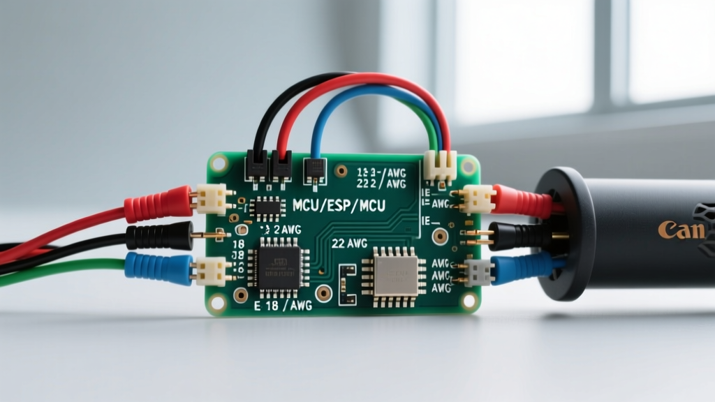
- Terminal 1 (CCW / Low): Wired to the Analog Common (ACM) or 0VDC reference. Use 18 AWG blue wire for DC common.
- Terminal 2 (Wiper): The variable signal output. Wired to the VFD's Analog Input (AI1). This is the most noise-susceptible node in the entire panel.
- Terminal 3 (CW / High): Wired to the +10VDC reference supply. Use 18 AWG red wire.
Panel Builder's Rule of Thumb: Never route the wiper signal directly through a standard terminal block without surge protection if the cable run exceeds 10 feet. Always use a signal isolator (e.g., Weidmuller ACT20P) for long-distance analog transmission to break ground loops between the HMI enclosure and the main MCC.
Component Selection Matrix: Pots, Wire & Breakers
Selecting industrial-grade components is non-negotiable. Consumer-grade carbon track pots will fail within months due to the mechanical vibration inherent in industrial environments. Below is a verified Bill of Materials (BOM) for a robust, UL-compliant analog control circuit.
| Component Type | Recommended Part / Spec | Technical Justification | Est. Unit Cost |
|---|---|---|---|
| Potentiometer | Bourns 53CAD-E28-B15 (10K Linear) | Conductive plastic element; 1M+ cycle life; IP40 panel seal. | $14.50 |
| Control Cable | Belden 8760 (18 AWG Shielded Twisted Pair) | Foil shield with drain wire; twists cancel out magnetic induction. | $1.20/ft |
| Circuit Breaker | ABB S201-C2 (1-Pole, 2A MCB) | DIN-rail mount; Curve C handles inrush from external PSUs. | $22.00 |
| Signal Isolator | Phoenix Contact MINI MCR-2-UI-REL | Galvanic isolation prevents VFD ground loops from frying the pot. | $185.00 |
| Terminal Block | WAGO 2002 Series (Double-Deck) | Spring-cage termination resists panel vibration loosening. | $4.10 |
Shield Grounding: The Panel Backplane Rule
The most critical point of failure in any pot wiring diagram involving shielded cable is improper shield termination. When analog signals are routed through a panel wire duct alongside 480VAC VFD output cables, high-frequency PWM switching noise capacitively couples onto the analog shield.
The Ground Loop Trap
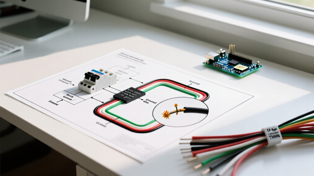
A common mistake is soldering the shield's drain wire to the potentiometer's metal housing or the 0VDC terminal. Because the HMI enclosure and the VFD backplane often sit at slightly different ground potentials, this creates a ground loop. Current will flow through the shield, introducing a 50/60Hz hum or high-frequency switching ripple directly into the VFD's analog input. The result is 'motor hunting'—the motor continuously oscillates around the set speed.
Correct Shield Termination Protocol
- Strip the Jacket: Remove the outer PVC jacket of the Belden 8760 cable within 3 inches of the panel cable entry gland.
- Clamp the Shield: Use a shield ground clamp (e.g., Weidmuller KLBUE 3-8) to secure the bare foil shield directly to the grounded metal panel backplane. This provides a 360-degree low-impedance path to earth ground for high-frequency noise.
- Isolate the Drain Wire: Trim the drain wire at the panel entry point. Do not connect it to the VFD's analog common terminal.
- Route to Terminals: Run only the twisted pair (Red, Blue, and White/Wiper) through the wire duct to the terminal blocks.
For authoritative guidance on signal separation and grounding, refer to the NFPA 79: Electrical Standard for Industrial Machinery, specifically Chapter 13, which mandates the physical separation of Class 1 power circuits and Class 2 analog signal circuits within panel wire ways.
Diagnostic Troubleshooting: Motor Hunting & Wiper Noise
Even with a perfect schematic, environmental factors can degrade analog performance. Use this diagnostic framework when troubleshooting erratic VFD behavior linked to the panel-mounted pot.
Symptom: Erratic Speed Fluctuations (Hunting)
Root Cause: VFD switching noise (often in the 2kHz to 16kHz range) is riding the wiper signal. The VFD's analog-to-digital converter interprets this noise as rapid speed commands.
Hardware Fix: Install a 0.1µF to 1.0µF ceramic capacitor directly across the AI1 (Wiper) and ACM (0V) terminals at the VFD. This creates a passive low-pass filter, shunting high-frequency noise to ground while allowing the DC voltage command to pass.
Software Fix: Increase the VFD's 'Analog Input Filter Time Constant' parameter (often found in the I/O menu). Setting this to 0.5 seconds will smooth out the noise, though it will introduce a slight lag in operator response.
Symptom: Dead Spots or Jumpy Voltage in Mid-Rotation
Root Cause: Mechanical vibration from adjacent contactors or heavy machinery has caused the carbon wiper to bounce or wear a physical trench into the resistive track.
Verification: Disconnect the wiper wire. Connect a Fluke 87V multimeter to the wiper and 0V terminals. Rotate the pot slowly. If the voltage skips or drops to zero intermittently, the element is destroyed.
Resolution: Replace the standard carbon pot with a Hybrid or Conductive Plastic potentiometer (e.g., Bourns 51 series). For extreme vibration environments, abandon the analog pot entirely and upgrade to a panel-mounted optical encoder with a digital up/down interface to the VFD.
Code Compliance: Wire Duct Separation
When executing this pot wiring diagram inside a UL 508A listed enclosure, physical routing is just as important as electrical termination. NEC Article 725 and NFPA 79 require that analog (Class 2/3) wiring and power (Class 1) wiring be separated by at least 2 inches in open panel space, or divided by a grounded metal barrier if sharing the same wire duct. If the analog signal wire must cross a 480VAC power line, it must do so at a strict 90-degree angle to minimize the surface area available for capacitive coupling. Failure to adhere to these separation rules will void the panel's UL listing and guarantee signal corruption in high-noise environments.