
The Subwoofer as a Linear Motor: Understanding the 2-Ohm Load
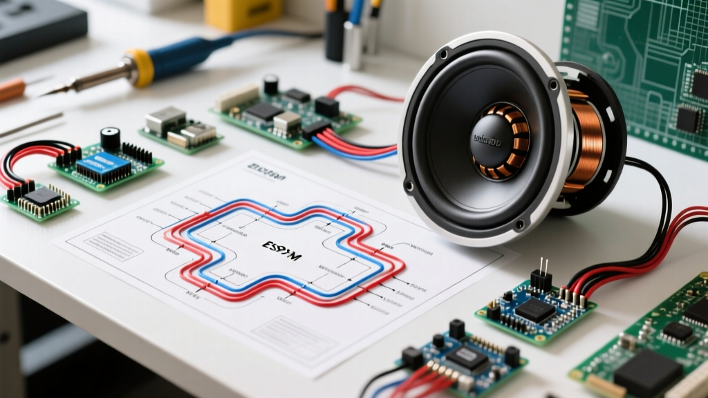
When approaching car audio installations from an electrical engineering perspective, it is critical to recognize that a subwoofer is not merely a speaker; it is a high-excursion linear electric motor. The voice coil acts as the armature, suspended within the magnetic field of the stator (the permanent magnet assembly). Wiring this motor requires a deep understanding of inductive loads, back-electromotive force (back-EMF), and thermal limits. Executing a precise 2 ohm wiring diagram for subwoofers is one of the most common and effective ways to maximize power transfer from modern Class D amplifiers while maintaining electrical stability.
Unlike simple resistive loads like heating elements or standard DC motors, a voice coil presents a complex, frequency-dependent impedance (Z). While we refer to the target configuration as a '2-ohm load,' a digital multimeter (DMM) measuring the DC resistance (Re) of a nominal 2-ohm voice coil will typically read between 1.6Ω and 1.8Ω. According to technical primers on speaker impedance and electrical loads, this discrepancy occurs because the AC impedance rises at the driver's resonant frequency (Fs) due to mechanical resonance and inductive reactance. Understanding this distinction is the first step in properly wiring and tuning your subwoofer system.
Common 2-Ohm Wiring Configurations
Achieving a final 2-ohm load at the amplifier terminals depends entirely on the voice coil architecture of your subwoofers. Below are the two most prevalent motor configurations used to achieve this target impedance.
Configuration A: Single Dual 4-Ohm Voice Coil (DVC)
This is the industry standard for high-power mobile audio. A single subwoofer features two separate 4-ohm voice coils (motors) on the same former. By wiring these two coils in parallel, you divide the impedance by two, resulting in a final 2-ohm load.
- Positive Terminal 1 connects to Positive Terminal 2 (Jumper wire).
- Negative Terminal 1 connects to Negative Terminal 2 (Jumper wire).
- Amplifier Positive connects to the joined Positive pair.
- Amplifier Negative connects to the joined Negative pair.
Configuration B: Two Single 4-Ohm Voice Coils (SVC)
When utilizing two separate subwoofers, each with a single 4-ohm voice coil, wiring them in parallel at the amplifier terminals yields a 2-ohm load. This configuration doubles the cone area and mechanical displacement, requiring significantly more current from the vehicle's charging system.
Impedance Matrix for Voice Coil Motors
To prevent catastrophic amplifier failure, you must calculate the final load before making any connections. The table below outlines the mathematical outcomes for common voice coil topologies.
| Subwoofer Configuration | Voice Coil Type | Wiring Topology | Final Amplifier Load |
|---|---|---|---|
| 1x Subwoofer | Dual 4-Ohm (DVC) | Parallel | 2 Ohms |
| 1x Subwoofer | Dual 2-Ohm (DVC) | Series | 4 Ohms |
| 2x Subwoofers | Single 4-Ohm (SVC) | Parallel | 2 Ohms |
| 2x Subwoofers | Dual 2-Ohm (DVC) | Series-Parallel | 2 Ohms |
| 1x Subwoofer | Single 2-Ohm (SVC) | Direct | 2 Ohms |
Step-by-Step Motor Wiring Execution
Treating the subwoofer as a high-current inductive motor dictates strict wiring protocols. Poor connections increase contact resistance, which acts as an unintended series resistor, reducing the amplifier's damping factor and causing thermal runaway at the terminal block.
- Wire Selection: Use 12 AWG Oxygen-Free Copper (OFC) wire for runs under 10 feet. For high-current systems exceeding 1000W RMS, upgrade to 8 AWG OFC to minimize voltage drop. Avoid Copper-Clad Aluminum (CCA), as its higher resistivity exacerbates thermal compression.
- Termination: Strip exactly 3/8-inch of insulation. Crimp using a closed-end ring terminal with an adhesive-lined heat shrink sleeve. Soldering the crimp is recommended for mobile environments subject to high vibration (up to 4G in trunk enclosures).
- Torque Specifications: When securing the ring terminals to the subwoofer's spring post or screw terminal, apply exactly 13 in-lbs (1.47 Nm) of torque. Overtightening strips the brass insert; undertightening causes micro-arcing and localized melting.
- Amplifier Damping Factor Check: At 2 ohms, the amplifier's damping factor is effectively halved compared to a 4-ohm load. This means the amplifier has less electromagnetic braking control over the voice coil motor. Ensure your enclosure is properly tuned (e.g., 32Hz for a standard ported box) to rely on Helmholtz resonance for mechanical unloading and motor control at the tuning frequency.
Amplifier Stability and Thermal Management in 2026
Modern Class D amplifiers have evolved significantly, utilizing high-speed MOSFET switching and advanced thermal management to handle 2-ohm loads with minimal efficiency loss. However, not all amplifiers are created equal. When wiring a 2-ohm load, you must verify the amplifier's continuous power rating at this specific impedance.
For example, the JL Audio RD1000/1 (retailing around $449 in 2026) is engineered to deliver a stable 1000W RMS at 2 ohms, utilizing a robust power supply and advanced convection cooling. Conversely, budget-tier amplifiers may claim '2-ohm stability' but will engage thermal protection circuits within 15 minutes of continuous high-excursion operation. As detailed in the Crutchfield wiring diagram and amplifier matching database, always match the amplifier's RMS output at 2 ohms to the subwoofer's thermal RMS handling capacity, ignoring peak or 'max' power ratings entirely.
Engineering Insight: Running an amplifier at 2 ohms generates significantly more heat in the output stage than at 4 ohms. Ensure the amplifier is mounted in a location with at least 1 inch of clearance on all sides for convective airflow, and never mount it directly to a subwoofer enclosure where acoustic vibration can fatigue the internal PCB solder joints.
Failure Modes and Troubleshooting the Inductive Load
When a 2-ohm subwoofer system fails, the root cause is almost always traceable to electrical abuse of the voice coil motor. Here is how to diagnose the most common failure modes using a DMM and an oscilloscope.
1. Thermal Compression and Power Drop
As the voice coil heats up during heavy bass transients, the copper wire's resistance increases. A 2-ohm coil measuring 1.7Ω at rest can swell to 3.5Ω or higher at 150°C. This phenomenon, known as thermal compression, reduces the current draw and dynamically alters the motor's Qts (total Q factor), resulting in 'muddy' or loose bass. Solution: Ensure the enclosure features adequate cooling vents or utilize subwoofers with aluminum voice coil formers, which act as heatsinks to dissipate thermal energy away from the copper windings.
2. Amplifier Clipping and DC Current Burnout
If the amplifier's input gain is set too high, the audio signal clips, transforming the AC waveform into a squared-off DC-like voltage. Because a voice coil motor relies on AC frequency to generate back-EMF (which naturally limits current flow), a clipped signal forces raw DC current through the coil. This causes rapid, catastrophic overheating, melting the voice coil former and jamming the motor in the magnetic gap. Solution: Use an oscilloscope to set the amplifier's gain structure, ensuring the output waveform remains clean up to the subwoofer's rated RMS voltage threshold (e.g., 44.7V RMS for a 1000W, 2-ohm load).
3. Inductive Kickback Damage
When an amplifier abruptly cuts power to a highly inductive 2-ohm load, the collapsing magnetic field of the voice coil can generate a high-voltage spike (inductive kickback). While premium amplifiers feature internal flyback diodes and over-voltage protection to absorb this energy, cheaper models may suffer blown output MOSFETs. Solution: Never disconnect subwoofer wiring while the amplifier is powered on, and ensure your amplifier features robust output-stage protection circuitry.
Final System Verification Checklist
Before applying power to your newly wired 2-ohm motor load, complete this final verification sequence:
- Verify all DMM readings at the amplifier terminals (expect ~1.6Ω to 1.8Ω for a 2-ohm nominal load).
- Confirm all terminal screws are torqued to 13 in-lbs.
- Ensure the amplifier's bass boost and subsonic filter are set correctly to prevent mechanical over-excursion below the enclosure's tuning frequency.
- Set the input gain using an oscilloscope or a high-quality digital multimeter measuring AC voltage at the speaker terminals.
By treating your subwoofer system as a precision linear motor rather than a simple audio accessory, you ensure maximum efficiency, longevity, and acoustic output from your 2-ohm configuration.