
The Anatomy of a Failing Soldering Station
Every technician and serious DIYer knows the sinking feeling of a cold solder joint on a dense, multilayer PCB. When your primary soldering iron for electronics repair begins to underperform, it is rarely a sudden, catastrophic failure. Instead, it is usually a compounding series of thermal, electrical, or mechanical degradations that slowly erode your tool's efficiency. A soldering station that takes five extra seconds to recover thermally might not seem like a big deal until you are trying to reflow a ground pad on a 10-layer motherboard, at which point that thermal lag results in a lifted pad or a damaged via.
Troubleshooting a precision soldering station requires a systematic approach. You must isolate the issue to one of three domains: thermal transfer (the tip and its interface), electrical generation (the heating element and sensor), or safety grounding (ESD protection). Below is a comprehensive diagnostic framework to help you identify and resolve the most common faults in modern electronics repair irons.
Diagnostic Matrix: Symptom to Solution
Before opening up your station's chassis or discarding a seemingly dead tip, cross-reference your symptoms with this diagnostic matrix. This will save you time and prevent unnecessary replacement part orders.
| Observed Symptom | Probable Root Cause | Primary Diagnostic Action |
|---|---|---|
| Solder balls up and refuses to wet the tip | Severe tip oxidation or iron plating degradation | Visual inspection under magnification; attempt chemical re-tinning |
| Station display flashes or reads 'H-E' / 'Error' | Broken thermocouple sensor or open heater circuit | Multimeter continuity and resistance test on handpiece pins |
| Iron heats up but temperature fluctuates wildly | Failing TRIAC on the station PCB or loose cord connection | Wiggle test on cord strain relief; oscilloscope check on heater output |
| Static shocks or blown MOSFETs during soldering | Loss of ESD ground path from tip to station chassis | Multimeter resistance test from tip apex to station ground pin |
| Iron works intermittently when moved | Internal copper strand fracture near the handpiece strain relief | Continuity test while physically manipulating the cord |
Domain 1: Thermal Transfer and Tip Oxidation
The most common reason a soldering iron for electronics repair appears 'broken' is actually a failure in thermal transfer, not heat generation. Modern lead-free solders, such as SAC305 (Tin/Silver/Copper), require higher operating temperatures—typically between 340°C and 380°C. At these elevated temperatures, the iron plating on your tip oxidizes rapidly if it is not continuously protected by a layer of molten solder.
Identifying Oxidation vs. Plating Erosion
Oxidation presents as a dark, crusty, blue-black layer on the tip. Solder will simply roll off this surface. According to Hakko's official maintenance guidelines, you should never use abrasive materials like sandpaper or files to clean a modern tip, as this will instantly destroy the microscopic iron plating, exposing the copper core to rapid dissolution by the tin in your solder.
The Re-tinning Protocol:
- Lower the station temperature to 250°C.
- Apply a generous amount of rosin-core solder and a specialized tip tinner (a mixture of solder powder and aggressive activator flux) to the oxidized area.
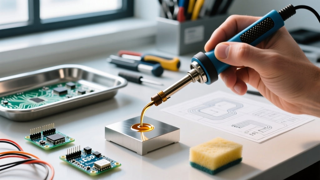
- Wipe gently on a damp cellulose sponge or brass wool (brass wool is preferred as it does not cause thermal shock).
- Immediately apply a thick coat of fresh, high-quality 63/37 SnPb solder to act as a sacrificial barrier before turning the station off.
If the tip remains unwettable after chemical tinning, the iron plating has likely suffered from 'solder leeching' (erosion), and the tip must be replaced.
Domain 2: Diagnosing the Heating Element and Sensor
If your station's digital display indicates an error, or if the iron remains completely cold despite the power indicator being on, the fault lies within the handpiece's internal ceramics or the connecting cord. Most modern stations, like the Hakko FX-888D or Weller WE1010, use a composite ceramic heater where the heating coil and the temperature sensor (thermocouple or RTD) are integrated into a single cartridge or tip-enclosed module.
Multimeter Testing Procedures
To diagnose a dead handpiece, you will need a digital multimeter set to the Ohms (Ω) range. Disconnect the handpiece from the station and probe the connector pins. While pinouts vary by manufacturer, the general diagnostic ranges are as follows:
- Heater Element: Measure across the primary heater pins. You should see a low resistance, typically between 2Ω and 10Ω. An 'OL' (Open Loop) reading indicates a snapped internal heater wire, requiring a handpiece or element replacement.
- Temperature Sensor: Measure across the sensor pins. Depending on whether the station uses a thermocouple or a PT100 RTD, you will typically read between 1Ω and 5Ω at room temperature. If this circuit is open, the station's microcontroller cannot read the tip temperature and will shut down the power to prevent a thermal runaway, triggering an error code on the display.
- Ground Pin: Measure from the designated ground pin to the actual metal tip. This must read less than 2Ω.
If the heater and sensor readings are within spec but the iron still fails to heat, the issue has moved upstream to the station's internal TRIAC (the solid-state relay that switches AC power to the heater) or the step-down transformer.
Domain 3: ESD Leakage and the Silent Component Killer
When utilizing a soldering iron for electronics repair on sensitive CMOS logic, RF modules, or bare MOSFET gates, Electrical Overstress (EOS) and Electrostatic Discharge (ESD) are critical concerns. A properly functioning ESD-safe soldering station bleeds static charges from the tip to the earth ground slowly, preventing a sudden spark that could punch through a transistor's gate oxide.
Testing for Ground Integrity and Leakage Voltage
Over time, the internal grounding wire inside the handpiece cord can fatigue and break, or the set screw connecting the tip sleeve to the ground wire can loosen. This creates a 'floating' tip. A floating tip can accumulate capacitive coupling from the AC heater element, inducing anywhere from 10V to 50V AC directly onto the tip.
To verify your ESD safety, perform this test based on IPC J-STD-001 standard recommendations for soldering equipment:
- Set your multimeter to AC Millivolts (mV).
- Place the black probe on a known, verified earth ground (like the ground pin of a wall outlet or your ESD mat's ground snap).
- Touch the red probe directly to the apex of your soldering tip while it is at operating temperature.
- The reading must be below 2.0 mV AC/DC. Anything higher indicates a compromised ground path or a failing isolation transformer inside the station.
Expert Insight: Never rely solely on the station's external ground lug to protect sensitive components. Always verify the tip-to-ground resistance with a multimeter weekly. As noted in NASA NEPP soldering reliability protocols, intermittent ground failures are a leading cause of latent defects in high-reliability aerospace electronics, and the same physics applies to your consumer repair bench.
Domain 4: Cord Fatigue and Strain Relief Failures
The umbilical cord connecting the handpiece to the base station is subjected to extreme mechanical stress. It is constantly twisted, pulled, and exposed to accidental burns from the very tool it powers. Intermittent power loss—where the iron cuts out when you twist your wrist—is almost always a cord failure.
High-end stations use silicone-jacketed cords with internal Kevlar or cotton strain relief fibers. However, the copper wires inside can still work-harden and snap right at the point where the cord enters the handpiece barrel. To confirm this, set your multimeter to the continuity beeper mode. Probe the heater pins at the station connector, then aggressively bend and wiggle the cord near the handpiece strain relief. If the multimeter beeps intermittently, the cord is internally fractured. Depending on your station's design, you may need to solder a replacement cord or replace the entire handpiece assembly.
Establishing a Preventative Maintenance Protocol
Troubleshooting is reactive; maintenance is proactive. To ensure your soldering iron for electronics repair maintains peak thermal recovery and ESD safety, implement the following bench rules:
- Never idle at high heat: If you are not actively soldering for more than 3 minutes, use the station's sleep function or manually drop the temperature to 200°C. Prolonged idling at 380°C accelerates tip oxidation by a factor of ten.
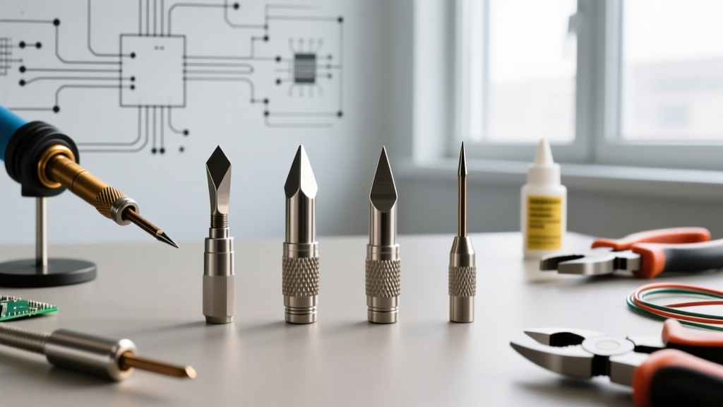
- Use the correct tip geometry: Using a fine conical tip (like an I-type) to solder large ground planes will force you to max out the temperature dial, stressing the heater. Match the tip's thermal mass to the pad size (e.g., use a chisel or bevel tip for heavy pours).
- Always tin before shutdown: The moment you power off the station, melt a large blob of rosin-core solder over the entire working surface of the tip. This sacrifices the solder to oxidation while the tip cools, preserving the iron plating underneath for your next repair session.
By understanding the interplay between thermal dynamics, electrical resistance, and ESD safety, you can keep your soldering station operating at factory specifications, ensuring reliable, IPC-compliant joints on every board you touch.