
Decoding the Soldering Iron Diagram: Beyond the Heating Element
Most hobbyists view a soldering iron as a simple plug-and-play thermal tool. However, when a station fails to heat, displays an error code, or exhibits dangerous thermal runaway, understanding the underlying soldering iron diagram becomes critical for effective repair and modification. In 2026, modern soldering stations are essentially high-power, closed-loop robotics end-effectors. They rely on complex feedback mechanisms to maintain thermal equilibrium at the tip-to-board interface.
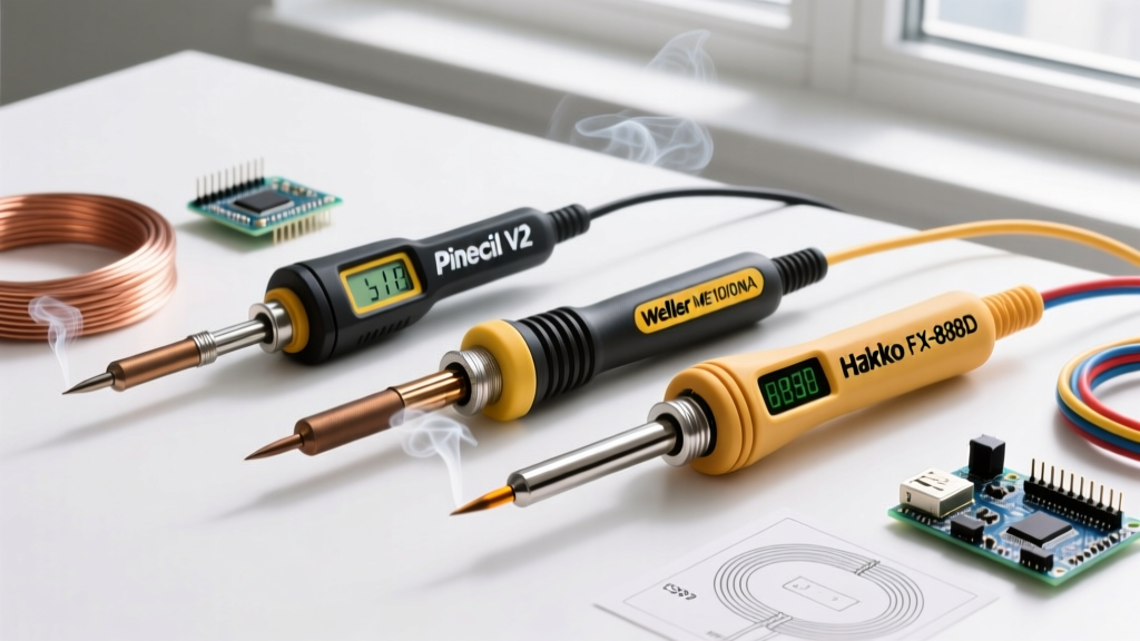
This feature deep dive dissects the electrical schematics, sensor feedback loops, and power topologies of industry-standard stations. Whether you are reverse-engineering a classic analog Weller WES51, troubleshooting a Hakko FX-888D, or analyzing the USB-C Power Delivery negotiation of a Pinecil V2, mastering the schematic is the key to advanced DIY electronics repair.
Core Power Topologies: Transformer vs. Switch-Mode (SMPS)
When you first examine a soldering iron diagram, the power supply section dictates the entire control architecture. Historically, stations utilized heavy, low-frequency step-down transformers. Today, the industry has bifurcated into two distinct schematic topologies:
1. The Analog TRIAC Topology (e.g., Weller WES51)
The schematic for a classic analog station reveals a 24V AC secondary winding feeding a zero-crossing detector and a TRIAC (often a BTA16 or similar silicon-controlled rectifier). The control logic relies on an LM358 dual operational amplifier. One half of the op-amp acts as an error amplifier, comparing the voltage set by the user's potentiometer against the micro-voltage generated by the iron's thermocouple. The second half drives the TRIAC gate via an optocoupler, phasing the AC waveform to deliver proportional power to the nichrome or ceramic heater.
2. The Digital DC-DC Buck & PWM Topology (e.g., Pinecil V2)
Modern portable irons like the Pinecil V2 eliminate the AC transformer entirely. Their soldering iron diagrams showcase a USB-C Power Delivery (PD) negotiation IC (such as the FUSB302B) requesting 20V at 3.25A from a GaN charger. The power is then routed through a high-efficiency P-channel MOSFET, driven by a Pulse Width Modulation (PWM) signal generated by a RISC-V microcontroller (like the Bouffalo Lab BL706). This allows for open-source firmware, such as the highly regarded IronOS project, to implement advanced PID (Proportional-Integral-Derivative) thermal algorithms that react to thermal loads in milliseconds.
The 4-Wire Ceramic Heater Standard (Hakko A1321)
To understand temperature regulation, we must look at the wand connector in the diagram. The Hakko A1321 ceramic heater is the gold standard for schematic analysis, utilizing a 4-pin or 5-pin configuration that separates the heating circuit from the sensing circuit.
- Pins 1 & 4 (Heater Core): Supplies the primary voltage to the ceramic resistive element. Expect a cold resistance of approximately 14Ω to 15Ω.
- Pins 2 & 3 (Thermocouple Sensor): Forms a closed loop with a Type-K or specialized proprietary thermocouple embedded in the ceramic. The cold resistance is incredibly low, typically between 1.5Ω and 2.5Ω.
- Pin 5 (Earth Ground): Ties the metal shaft and tip directly to the mains earth ground for electrostatic discharge (ESD) safety.
Expert Insight: If your station's schematic shows a 2-wire connection (common in cheap, unregulated clones or basic TS100 setups), the microcontroller must use 'Time Division Multiplexing' (TDM). It rapidly switches the power off for a few milliseconds to read the back-EMF or resistance of the heater trace itself to estimate temperature. This is inherently less accurate than a dedicated 4-wire thermocouple loop.
Comparative Soldering Iron Diagram Matrix
Below is a technical comparison of the internal schematic architectures across three dominant paradigms in the 2026 market:
| Station Model | Power Topology | Control Logic / IC | Heater Type | Feedback Sensor |
|---|---|---|---|---|
| Weller WES51 | 24V AC Transformer | Analog LM358 Op-Amp + TRIAC | Nichrome / Ceramic | Integrated Thermocouple |
| Hakko FX-888D | 24V AC Transformer | Digital MCU + Zero-Cross SSR | Ceramic (A1321) | Dedicated Thermocouple |
| Pinecil V2 | USB-C PD (DC 12-24V) | BL706 RISC-V + MOSFET PWM | Direct DC Resistive | Op-Amp Trace Sensing |
Advanced Troubleshooting Using Schematic Tracing
When a digital station like the Hakko FX-888D flashes an 'H-E' (Heater Error) on its LED display, the internal microcontroller has detected an open or short circuit in the wand loop. By referencing the soldering iron diagram, you can isolate the fault systematically rather than blindly replacing parts.
Step-by-Step Multimeter Diagnostics
- Isolate the Wand: Unplug the station from AC mains. Disconnect the wand from the base station PCB to eliminate board-level component interference.
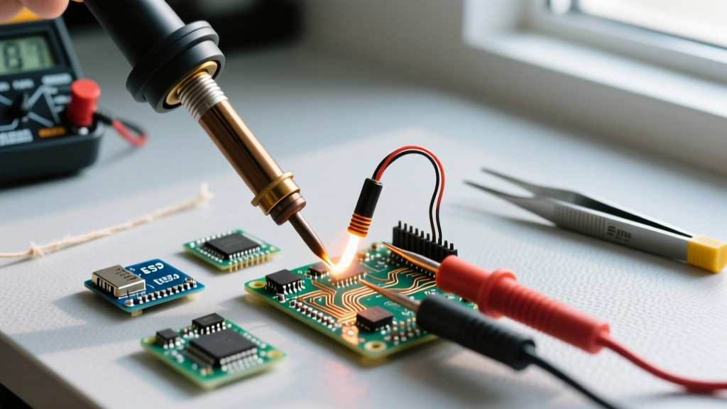
- Test the Heater Core: Set your multimeter to the 200Ω range. Probe pins 1 and 4 on the wand's DIN connector. A reading of infinity (OL) indicates a snapped internal heater wire. A reading near 14Ω confirms the heater is intact.
- Test the Sensor Loop: Probe pins 2 and 3. You should see roughly 2Ω. If the schematic shows a series protection resistor on the PCB (often a 10Ω 1/4W film resistor), check it for continuity. Blown protection resistors are a primary cause of false 'H-E' codes.
- Check for Ground Faults: Set the multimeter to continuity mode. Place one probe on the soldering tip itself and the other on Pin 5 (Ground). You must hear a beep. If the circuit is open, your tip is not ESD-safe, risking destruction of sensitive MOSFETs and microcontrollers on your workbench.
ESD Grounding and Safety Topologies
In any professional-grade soldering iron diagram, you will notice a dedicated, uninterrupted grounding path connecting the metal tip, through the wand shaft, to the earth ground pin of the AC mains plug. According to the ESD Association standards for electronics assembly, this equipotential bonding is non-negotiable when handling static-sensitive components.
Cheap, unregulated irons often omit this ground wire entirely to save on manufacturing costs, relying on a 2-prong polarized plug. If you are modifying a DIY station or repairing a vintage schematic, always verify that the tip-to-earth resistance is strictly under 10Ω. Furthermore, ensure that any Y-capacitors bridging the primary and secondary sides of the SMPS transformer are rated for safety (e.g., 250VAC X2/Y2 certified) to prevent lethal mains voltage from coupling onto the iron's tip via capacitive leakage.
Understanding Thermocouple Signal Conditioning
The raw output of a thermocouple is incredibly small—often in the microvolt range per degree Celsius. As detailed in technical literature by Analog Devices, the Seebeck effect requires precise cold-junction compensation (CJC) and high-gain, low-noise amplification.
When analyzing the analog front-end (AFE) of a soldering iron schematic, look for:
- Instrumentation Amplifiers: Used to reject common-mode noise induced by the 50/60Hz AC heater field.
- Low-Pass Filtering: RC networks designed to filter out the high-frequency PWM switching noise generated by the MOSFET or TRIAC.
- Cold-Junction Diodes: Semiconductor junctions located on the PCB near the wand connector to compensate for ambient room temperature shifts.
Frequently Asked Questions
Can I use a DC power supply with an AC transformer-based station?
No. If the soldering iron diagram specifies a 24V AC transformer and utilizes a TRIAC for phase-angle control, applying 24V DC will cause the TRIAC to latch permanently 'ON' once triggered. This results in immediate thermal runaway, potentially melting the wand handle or causing a fire. Always match the power topology to the schematic's design.
Why do some schematics show a diode in series with the heater?
A series diode (often a 1N4007) is sometimes used in 'standby' or 'sleep' circuits. It acts as a half-wave rectifier, effectively cutting the RMS voltage to the heater by 50% when the iron is placed in its cradle, dropping the tip temperature to a safe 200°C to prevent tip oxidation while conserving energy.
How do I read the pinout on a 5-pin DIN connector diagram?
Always view the DIN connector from the solder side (the back of the female receptacle on the base station) or the wire side of the male plug. Standard Hakko 5-pin layouts typically map Pin 1 and 4 to the heater, Pin 2 and 3 to the sensor, and Pin 5 to the shield/ground. Always verify with a multimeter against the physical wand before applying power.