
The Cartridge Paradigm: Why C245 Dominates Precision Rework
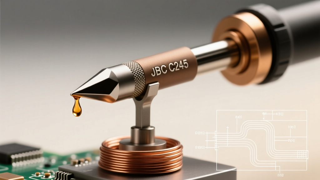
In the landscape of professional electronics rework, the transition from traditional composite tips to integrated cartridge systems fundamentally altered thermal management. At the forefront of this shift is the JBC T245 handle ecosystem, which utilizes C245 soldering iron tips. Unlike legacy systems where the heating element, thermal sensor, and copper tip are three separate mechanical components separated by air gaps and oxidation layers, the C245 architecture integrates the heater, thermocouple, and tip into a single, unified cartridge.
This feature deep dive dissects the engineering, thermal dynamics, and practical geometries of C245 soldering iron tips. Whether you are reworking high-density 0402 SMD components or soldering heavy 10 AWG wires to massive ground planes, understanding the specific capabilities of the C245 lineup is critical for achieving IPC J-STD-001 compliant solder joints without inducing thermal shock to sensitive silicon.
Thermal Mass and Recovery: The 2-Second Rule
The primary advantage of C245 soldering iron tips lies in their thermal mass distribution. In a standard ceramic heater setup (like the ubiquitous Hakko FX-888D), heat must travel from the ceramic core, through an air gap, and into the hollow base of the tip. This creates thermal lag. When the tip contacts a high-thermal-mass joint, the tip temperature plummets, and the sensor—located inside the heater, not the tip—takes several seconds to register the drop and request more power.
In the C245 system, the thermocouple is positioned mere millimeters from the very edge of the tip. When paired with a 130W JBC station (such as the CD-2B or DDE-2B), the system detects a thermal drop the instant the tip touches a copper pour. The station dumps maximum current into the integrated heater, achieving a recovery time of under 2 seconds. This rapid response allows technicians to run lower baseline temperatures (typically 320°C to 340°C), drastically reducing flux burn-off and tip oxidation while maintaining flawless wetting.
C245 Tip Geometry Matrix: Selecting the Right Profile
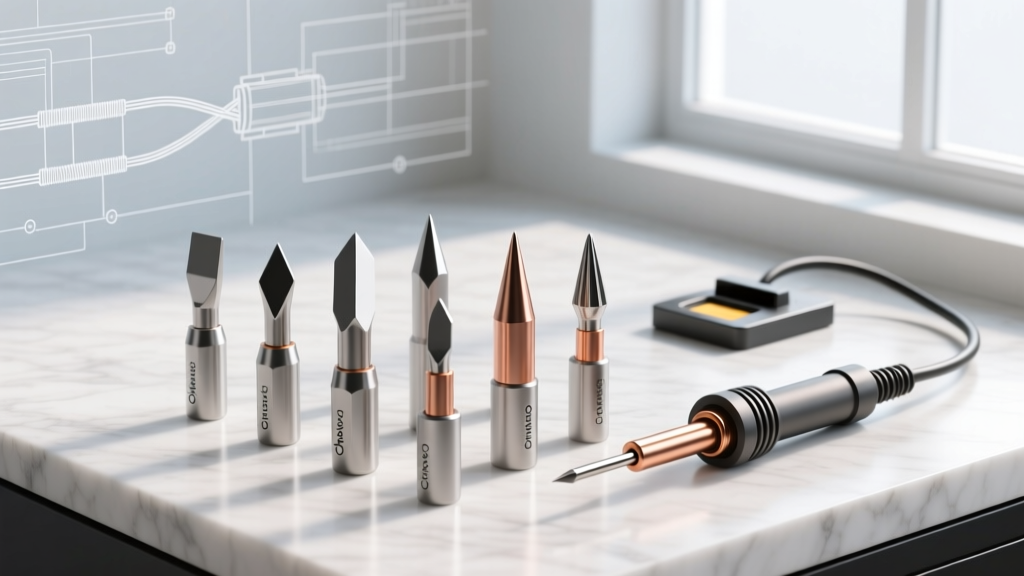
Choosing the correct tip geometry is just as critical as temperature control. Using an undersized tip on a ground plane results in cold joints, while an oversized tip on a 0.5mm pitch QFP risks bridging. Below is a structural breakdown of the most essential C245 profiles utilized in modern 2026 rework environments.
| Tip Model | Profile Type | Dimensions (W x L) | Primary Application | Thermal Mass Rating |
|---|---|---|---|---|
| C245-112 | Chisel | 1.2mm x 4.5mm | General SMD, 0603/0805, standard TH | Medium |
| C245-945 | Blade / Knife | 4.5mm (Edge) | Drag soldering, QFN pads, scraping | High |
| C245-008 | Conical | 0.8mm (Diameter) | Precision 0402/0201, micro-vias | Low |
| C245-116 | Heavy Chisel | 1.6mm x 6.0mm | Multi-layer TH, heavy ground planes | Very High |
| C245-764 | Drag / Hoof | 3.5mm (Concave) | SOIC/TQFP drag soldering, tinning | High |
Navigating SMD Drag Soldering with the C245-945
The C245-945 blade tip is an industry standard for drag soldering fine-pitch ICs. The technique relies on surface tension rather than mechanical wiping. By applying a generous layer of no-clean or RMA flux to the pads, setting the station to 330°C, and loading the blade with a moderate amount of 63/37 or SAC305 solder, the technician can drag the tip across the pins in a single, fluid motion. The blade's high thermal mass ensures the solder remains fully molten, while the sharp edge prevents bridging. According to NASA Workmanship Standards for soldered connections, proper wetting and fillet formation during drag soldering require consistent thermal delivery, which the 945 cartridge excels at providing.
Tackling Heavy Ground Planes with the C245-116
When soldering thick through-hole connectors to 4-layer or 6-layer PCBs with internal copper pours, thermal dissipation is the enemy. The C245-116 heavy chisel provides the necessary surface area to transfer 130W of energy directly into the barrel of the via. Pro-Tip: Pre-heat the board to 100°C using a bottom-side preheater before applying the C245-116. This reduces the thermal delta, preventing the delamination of the PCB's copper layers and ensuring a smooth, volcano-shaped fillet.
Maintenance Protocols and Failure Modes
Despite their advanced engineering, C245 soldering iron tips are consumables. The iron plating that protects the copper core from galvanic corrosion is typically only 0.1mm thick. Understanding failure modes is essential for maximizing the lifespan of your $40+ cartridges.
- Oxidation and Blackening: Occurs when the tip is left at high temperatures (above 380°C) without a solder coating. The flux burns away, exposing the iron plating to oxygen. Solution: Always tin the tip heavily before placing it in the holster.
- Pitting and Dissolution: Caused by using highly acidic fluxes (like certain plumbing or zinc-chloride fluxes) or excessive mechanical abrasion. Never use C245 tips on non-electronics plumbing applications.
- Improper Cleaning: Using a soaking wet cellulose sponge causes rapid thermal shock, which can micro-fracture the internal ceramic heater or degrade the thermocouple junction. Always use a dry brass wire sponge (such as the JBC CLS-A) to clean the tip without dropping its temperature.
Expert Insight: If a C245 tip becomes oxidized and refuses to wet, do not scrape it with a knife or sandpaper. This instantly destroys the iron plating and ruins the cartridge. Instead, use a specialized tip tinner/cleaner paste (like JBC T245-C). Dip the hot tip into the paste for 3 seconds, then wipe on brass wool. The mild abrasives and active flux in the paste will strip the oxidation and re-tin the surface simultaneously.
The Counterfeit Cartridge Crisis: OEM vs. Clone
As of 2026, the secondary market is flooded with counterfeit C245 tips priced between $6 and $12, compared to the $38 to $45 USD commanded by genuine JBC OEM cartridges. While the physical dimensions of these clones may fit the T245 handle, their internal engineering is severely compromised.
The Thermocouple Drift Problem
Genuine C245 tips utilize high-grade, precision-calibrated thermocouple wire that interfaces perfectly with the JBC station's microcontroller. Clone manufacturers often use cheaper, lower-gauge alloys to cut costs. This results in significant voltage drops and thermal miscalibration. A station may display 350°C, while the actual tip temperature fluctuates wildly between 310°C and 390°C. This unpredictability is catastrophic when reworking temperature-sensitive components like MLCCs (Multi-Layer Ceramic Capacitors), which are highly susceptible to thermal cracking, or BGAs that require precise reflow profiles.
Plating Thickness and Lifespan
Metallurgical analysis of clone tips frequently reveals an iron plating thickness of less than 0.03mm, compared to the robust plating on OEM tips. When exposed to molten SAC305 (tin-silver-copper) solder, which is highly corrosive to iron, clone tips exhibit severe pitting and dissolution within 20 to 30 hours of active use. Genuine C245 tips, when maintained with proper sleep-mode protocols and brass wool cleaning, routinely exceed 500 hours of active rework time. The false economy of clone tips ultimately costs more in ruined PCB pads, damaged components, and constant replacement downtime.
Final Verdict: Maximizing Your C245 Investment
The C245 ecosystem remains the gold standard for mid-to-high volume precision electronics rework. By matching the specific geometry to your application—utilizing the C245-008 for micro-SMD, the C245-112 for general assembly, and the C245-945 for drag soldering—you leverage the full 130W thermal recovery potential of the cartridge. Combine this with strict adherence to industry-leading solder chemistry practices, proper brass-wool maintenance, and a strict refusal to use uncalibrated clones, and your C245 setup will deliver flawless, IPC-compliant joints for years to come.