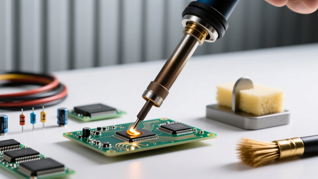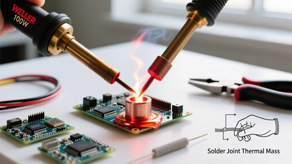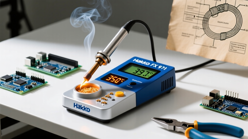

The Direct Answer: How Hot Are Soldering Irons?
When technicians ask, 'how hot are soldering irons,' the answer spans a wide operational spectrum. A standard electronics soldering iron operates between 300°C and 400°C (572°F to 752°F). However, the maximum temperature capability of modern digital soldering stations typically ranges from 200°C (392°F) up to 450°C (842°F), with specialized heavy-duty irons for plumbing or stained glass pushing past 500°C (932°F).
But setting your station to 400°C does not mean the joint reaches 400°C. Soldering is an exercise in thermodynamics, not just temperature. The goal is to transfer enough thermal energy to melt the solder alloy and achieve proper metallurgical wetting within a specific dwell time (usually 1.5 to 3 seconds), without exceeding the thermal limits of the PCB substrate or the component packaging.
Temperature vs. Thermal Recovery: The Wattage Factor
A common misconception among beginners is that a higher temperature setting guarantees faster soldering. In reality, thermal recovery rate—dictated by the station's wattage and the tip's thermal mass—is far more critical.
If you are using a 40W iron set to 350°C and apply it to a large copper ground plane, the copper will rapidly act as a heatsink, pulling the tip temperature down to 250°C in seconds. The solder will fail to flow, resulting in a cold joint. Conversely, a 70W station like the Weller WE1010NA or the Hakko FX-888D will detect the temperature drop via its thermocouple and pump more current into the ceramic heating element to maintain the 350°C setpoint.
Expert Rule of Thumb: Never compensate for a lack of wattage or poor thermal mass by simply cranking up the temperature. Running a low-wattage iron at 420°C to solder a thick wire will oxidize the tip instantly and burn the flux before the core of the wire reaches the solder's melting point.
Solder Alloy Melting Points and Iron Settings Matrix
To determine the correct iron temperature, you must first know the melting point of your solder alloy. According to metallurgical data from Kester's solder specifications, the iron tip must be set approximately 100°C to 150°C above the alloy's liquidus point to ensure rapid heat transfer.
| Solder Alloy | Application | Melting Point (Liquidus) | Recommended Iron Temp | Target Dwell Time |
|---|---|---|---|---|
| 63/37 Sn/Pb (Eutectic) | General DIY, Prototyping | 183°C (361°F) | 300°C - 330°C | 1 - 2 seconds |
| SAC305 (Sn96.5/Ag3.0/Cu0.5) | Commercial Lead-Free (RoHS) | 217°C - 220°C (422°F - 428°F) | 340°C - 370°C | 2 - 3 seconds |
| Sn95/Sb5 | High-Temp / Automotive | 235°C - 240°C (455°F - 464°F) | 360°C - 390°C | 2 - 4 seconds |
| 50/50 Sn/Pb | Plumbing, Stained Glass | 183°C - 215°C (361°F - 419°F) | 360°C - 400°C | 3 - 5 seconds |
Application-Specific Temperature Profiles
Different physical masses require different thermal strategies. Here is how to set your station based on the specific task at hand, adhering to the workmanship requirements outlined in IPC J-STD-001 standards.
1. Delicate SMD Components (0402, 0603, QFN)
- Target Temperature: 300°C - 320°C (572°F - 608°F)
- Tip Selection: Micro-pencil or fine conical (e.g., Weller RT1 or JBC 115/108).
- Technique: Use a lower temperature to prevent lifting the microscopic pads off the PCB. Apply a generous amount of high-quality tacky flux (like Amtech NC-559) to lower the surface tension and allow the solder to flow at lower thermal inputs.
2. Standard Through-Hole Components (DIP ICs, Resistors, Capacitors)
- Target Temperature: 330°C - 350°C (626°F - 662°F)
- Tip Selection: 1.2mm to 2.4mm chisel tip (e.g., Hakko T18-D12 or T18-D24).
- Technique: Heat the lead and the plated through-hole pad simultaneously. Feed 0.8mm (0.031 inch) rosin-core solder into the joint, not directly onto the iron tip. As detailed in SparkFun's through-hole soldering guide, feeding solder onto the iron creates a thermal bridge but often leads to flux burn-off before the pad is hot enough.
3. Heavy Ground Planes and Multilayer PCBs
- Target Temperature: 380°C - 400°C (716°F - 752°F)
- Tip Selection: High thermal mass bevel or wide chisel (e.g., Weller RT4 or Hakko T18-D52).
- Technique: Internal copper layers act as massive heatsinks. If your station struggles to maintain temperature, use a PCB preheater (like the Puhui T-8280) set to 100°C to reduce the thermal delta between the board and the iron.
4. Wires and Connectors (14 AWG to 24 AWG)
- Target Temperature: 350°C - 380°C (662°F - 716°F)
- Tip Selection: Chisel or bevel tip matching the wire gauge.
- Technique: Pre-tin both the wire and the connector lug separately before joining. Stranded copper has high surface area and dissipates heat quickly; a higher temperature ensures the solder wicks deep into the strands via capillary action.
Failure Modes: The Cost of Incorrect Temperatures
Operating outside the optimal thermal window introduces severe reliability risks to your electronic assemblies.
When the Iron is Too Cold (Under 280°C for Lead-Free)
- Cold Solder Joints: The flux may activate, but the base metals fail to reach the temperature required for intermetallic compound (IMC) formation. The joint looks grainy, dull, and spherical, exhibiting high electrical resistance and mechanical fragility.
- Tombstoning: In SMD work, uneven heating caused by lingering too long with a low-temp iron can cause one pad to reflow before the other, pulling the component upright.
When the Iron is Too Hot (Over 400°C for Standard PCBs)
- Flux Burn-Off: Rosin and synthetic fluxes carbonize above 380°C, leaving a hard, black, non-conductive residue that actively prevents solder wetting and is incredibly difficult to clean with standard isopropyl alcohol.
- Pad Delamination: Standard FR4 PCB laminates have a Glass Transition Temperature (Tg) between 130°C and 170°C. While they can withstand brief excursions above this, holding a 420°C iron on a pad for more than 4 seconds will cause the epoxy resin to break down, blister, and lift the copper pad entirely off the board.
- Rapid Tip Oxidation: At temperatures exceeding 400°C, the iron plating on the tip oxidizes at an exponential rate. The solder will 'ball up' and roll off the tip (de-wetting), destroying a $15 replacement tip in a matter of hours.
Pro-Tips for Thermal Management and Calibration
To ensure your soldering iron is actually at the temperature the digital display claims, follow these professional maintenance protocols:
- Ditch the Wet Sponge: Wiping a 350°C tip on a water-soaked cellulose sponge causes an instantaneous thermal shock, dropping the tip temperature by 50°C to 100°C and micro-fracturing the iron plating over time. Switch to a dry brass wire sponge (like the Hakko 599B) which cleans the tip without robbing it of thermal energy.
- Verify with a Thermocouple: Digital displays measure the heat at the base of the heating element, not the very tip of the iron. Use a K-type thermocouple with a surface probe and a dab of thermal paste to measure the actual tip temperature. If it deviates by more than 10°C, use the station's offset calibration menu to correct it.
- Always Tin Before Storing: Never turn off your station with a clean, shiny tip. The moment the heater powers down, the tip will oxidize as it cools. Apply a thick blob of cheap, leaded 60/40 solder to the tip right before powering off. This sacrificial layer will oxidize instead of the tip's iron plating, ensuring perfect wetting the next time you power up.