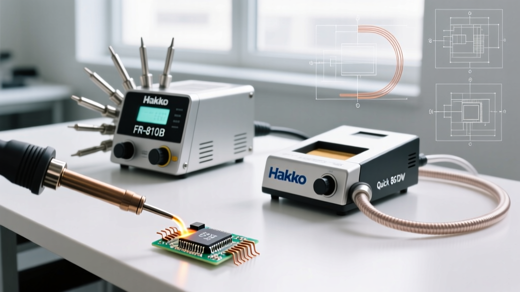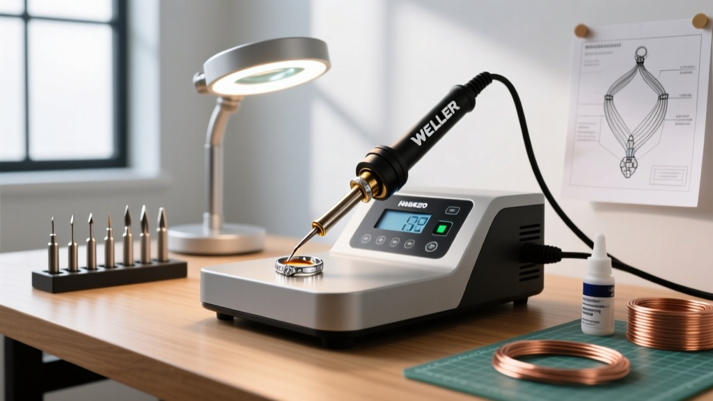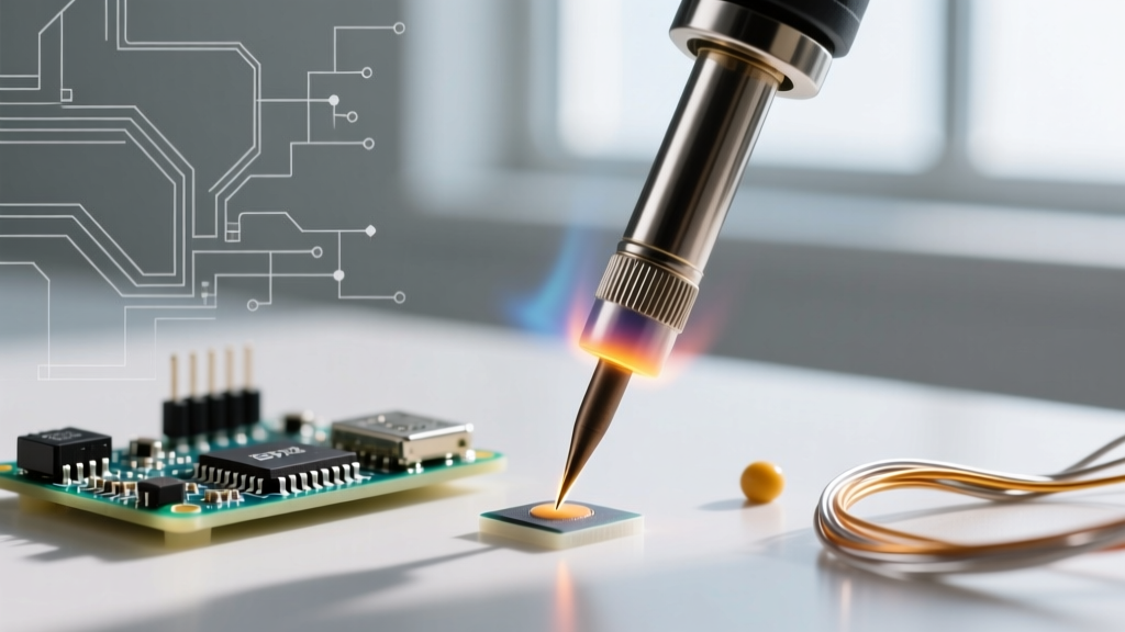

When transitioning from standard through-hole components to surface-mount devices (SMDs) like 0402 resistors, 0201 capacitors, or 0.4mm-pitch Quad Flat No-leads (QFNs), the margin for error shrinks to fractions of a millimeter. As of 2026, the miniaturization of consumer wearables and IoT sensors has made micro-soldering a mandatory skill for electronics repair and prototyping. At this scale, your choice of a fine soldering iron and your underlying technique dictate the difference between a reliable, IPC-compliant joint and a catastrophic bridged pad.
The Physics of Micro-Soldering: Why Standard Irons Fail
A common mistake among intermediate hobbyists is attempting to solder 0402 components (measuring just 1.0mm x 0.5mm) with a standard 60W soldering iron and a fine conical tip. The issue is not just the tip size; it is thermal mass and transfer rate. A standard iron relies on a large thermal reservoir. When a massive chisel or thick conical tip touches a micro-pad, the heat transfer is bottlenecked by the tip's geometry and oxidation. Furthermore, standard irons suffer from thermal lag—the sensor is located deep in the heating element, far from the tip's apex, resulting in overshooting temperatures that instantly vaporize no-clean flux and lift delicate PCB traces.
Selecting the Right Fine Soldering Iron System
To achieve the 2-second thermal recovery required for micro-SMD work, you need a system with the heating element integrated directly into the tip cartridge. Below is a comparison of the top-tier micro-soldering systems dominating the market in 2026.
| System | Handle Model | Tip Series | Recovery Time | Approx. Cost (2026) |
|---|---|---|---|---|
| JBC | T245 / C245 | C245 (e.g., C245-111) | < 2 seconds | $450 - $520 |
| Weller | WXMP | RT 3 (e.g., RT3MS) | ~ 4 seconds | $350 - $400 |
| Hakko | FM-2032 | T31 Series | ~ 6 seconds | $280 - $320 |
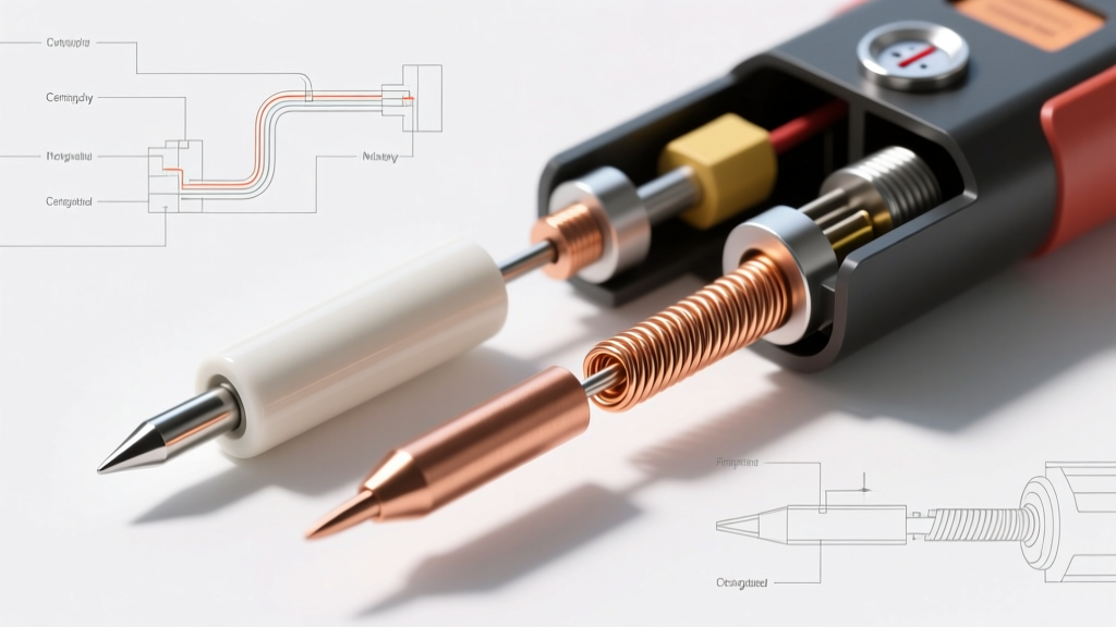
For dedicated micro-soldering, the JBC T245 handle is widely considered the gold standard. Its cartridge design places the thermocouple less than 1mm from the tip's edge, allowing the station to dump up to 75W of power instantly when a thermal drop is detected. This prevents the operator from having to compensate for heat loss by cranking up the base temperature, which degrades both the PCB pad and the flux.
Tip Geometry: Beyond the Standard Micro-Pencil
Counterintuitively, the ultra-fine 0.1mm conical tip is often the worst choice for micro-soldering. Conical tips have a very small surface area at the point of contact, leading to poor thermal transfer and a high susceptibility to oxidation. Instead, experts rely on the following geometries:
- Micro-Chisel (0.4mm to 0.7mm): The flat face maximizes surface area contact with the SMD lead and the PCB pad simultaneously. A 0.4mm micro-chisel (like the JBC C245-903) is ideal for 0402 and 0603 components.
- Knife Tip (1.5mm to 2.0mm): Essential for drag-soldering fine-pitch ICs (0.5mm or 0.4mm pitch). The knife edge allows you to channel molten solder across 20+ pins in a single, fluid motion while relying on flux's surface tension to prevent bridging.
- Micro-Spatula / Blade: Used for scraping away solder bridges on 0.2mm BGA edge pads or cleaning up QFN thermal vias.
Thermal Profiles and Temperature Settings
According to the IPC J-STD-001 standards for soldered electrical assemblies, the goal is to form a proper intermetallic compound (IMC) layer—typically 1 to 3 microns thick—without exceeding the thermal degradation limits of the PCB substrate (usually FR-4, which begins to suffer at prolonged exposures above 260°C).
Expert Rule of Thumb: Never set your fine soldering iron above 350°C (662°F) for standard SMD work. If you find the solder isn't melting, your tip is oxidized, your flux is depleted, or your iron lacks the active thermal recovery to maintain heat at the joint. Increasing the temperature will only accelerate tip death and risk pad delamination.
Recommended Baseline Temperatures
- Sn63/Pb37 (Leaded Eutectic): 300°C - 320°C. Melts at 183°C. The wide plastic window makes it highly forgiving for hand-soldering micro SMDs.
- SAC305 (Lead-Free): 340°C - 360°C. Melts at 217°C-220°C. Requires a high-recovery active iron (like the JBC or Weller WXMP) to prevent cold joints, as lead-free solder has a narrower plastic phase and higher surface tension.
Flux Dynamics and Solder Paste Selection
When working with a fine soldering iron, flux is not an accessory; it is the primary driver of the soldering process. Flux removes oxidation, promotes wetting, and creates a surface tension envelope that prevents solder bridges on 0.4mm pitch pins.
For micro-SMD rework, liquid fluxes (like Kester 951) evaporate too quickly under the intense, localized heat of a micro-chisel tip. Instead, use a high-tack, no-clean gel flux such as MG Chemicals 8341 or Chip Quik NC191. Apply a micro-dot using a 22-gauge dispensing needle or a fine-tipped flux pen. As noted in SparkFun's comprehensive SMD soldering guide, the tackiness of the flux also serves a secondary mechanical purpose: it holds the tiny 0402 component in place while you bring the iron to the first pad.
Wire vs. Paste for Micro Joints
While 0.3mm diameter rosin-core solder wire is available, it is often too thick for 0201 components, leading to massive, tombstoning-prone blobs. For components smaller than 0603, switch to Type 4 or Type 5 Solder Paste (e.g., Chip Quik SMD4300). Dispense a microscopic dot on the pad, place the component with fine tweezers, and touch the pad with your fine soldering iron. The paste will reflow instantly, wicking perfectly under the component leads via capillary action.
Step-by-Step: Drag Soldering a 0.4mm Pitch QFN
Drag soldering with a fine knife tip is the most efficient way to solder multi-pin ICs. Here is the exact workflow used by board-level repair technicians:
- Prep and Flux: Clean the PCB pads with 99% isopropyl alcohol (IPA). Apply a thin, even layer of tacky flux across all pads.
- Component Placement: Using Dumont #5 tweezers, align the QFN. The pin-1 indicator must match the silkscreen. Press down gently; the flux will hold it.
- Anchor Two Corners: Switch to your 0.4mm micro-chisel tip. Apply a tiny amount of 0.5mm leaded solder to two diagonally opposite corner pins to lock the IC in place.
- Switch to Knife Tip: Install a 1.5mm or 2.0mm knife tip. Set the iron to 330°C.
- The Drag: Melt a small bead of solder onto the knife edge. Hold the iron at a 45-degree angle. Gently drag the bead across the pins in one continuous motion. The flux's surface tension will pull the solder into individual fillets.
- Desoldering Wick Cleanup: Inevitably, 2 or 3 pins will bridge. Do not panic. Apply a fresh drop of liquid flux, lay a piece of 1.0mm copper desoldering braid (wick) over the bridges, and press down lightly with the knife tip. The wick will absorb the excess solder via capillary action, leaving perfect, IPC-A-610 Class 2 compliant fillets.
Maintenance and Tip Longevity for Micro-Tips
Fine soldering iron tips have a microscopic iron-plating layer over the copper core. Once this plating is breached or oxidized, the tip is dead. To maximize the lifespan of your $40 micro-cartridges:
- Never use abrasive sponges. Use a brass wire sponge (curly brass wool) to clean the tip. Damp cellulose sponges cause rapid thermal shock, which leads to micro-fractures in the iron plating.
- Always leave a sacrificial solder blob. Before placing the iron back in its holder, melt a large blob of cheap, leaded solder over the entire working surface. This acts as a sacrificial oxidation barrier. Clean it off on the brass sponge only when you are ready to make the next joint.
- Use tip tinner sparingly. Chemical tip tinner is highly abrasive. Use it only as a last resort to rescue a severely oxidized tip, and immediately re-tin with fresh solder afterward.
Mastering the fine soldering iron is less about having the steadiest hands and more about understanding thermal dynamics, fluid mechanics (flux and wetting), and geometry. By investing in an active-thermal system, selecting the correct chisel or knife geometry, and respecting the thermal limits of your PCB, you can reliably assemble and repair micro-SMD boards that rival factory-line automated optical inspection (AOI) standards.