
The Core Purpose: What Is Flux Used For When Soldering?
If you have ever examined a dull, grainy solder joint and wondered why it failed to bond, you have encountered the exact problem flux is engineered to solve. When asking what is flux used for when soldering, the answer lies in surface chemistry and thermodynamics. At its core, flux is a chemical cleaning agent that removes metal oxides, prevents further oxidation during heating, and reduces the surface tension of molten solder to promote 'wetting'.
Without flux, the ambient oxygen in the air reacts with the heated copper pad and component lead, forming a microscopic layer of copper oxide (CuO) and tin oxide (SnO2). Molten solder cannot bond to oxidized metal; it simply beads up and rolls off, much like water on a freshly waxed car. Flux dissolves this oxide barrier, exposing the pristine base metal and allowing the solder to form a true intermetallic compound (IMC) layer.
The Science of Wetting and Surface Tension
To understand how to apply flux correctly, you must understand the physics of wetting. Wetting is the ability of a liquid to maintain contact with a solid surface. In soldering, we measure this via the 'contact angle'.
- Ideal Wetting: Contact angle less than 30 degrees. The solder flows out into a smooth, concave fillet.
- Partial Wetting: Contact angle between 30 and 90 degrees. The joint is mechanically weak and electrically unreliable.
- Non-Wetting (Dewetting): Contact angle greater than 90 degrees. The solder beads up, indicating a complete failure of the flux to remove oxides.
By lowering the surface tension of the molten alloy (such as SAC305 or Sn63Pb37), flux allows capillary action to draw the solder into plated through-holes (PTH) and under fine-pitch surface mount device (SMD) leads.
Decoding Flux Chemistry: Selecting the Right Formulation
Not all fluxes are created equal. The IPC J-STD-004 standard categorizes fluxes based on their base material and activator strength. Choosing the wrong chemistry can lead to either insufficient cleaning or severe post-assembly corrosion.
| Flux Category | Base Chemistry | Activator Strength | Cleaning Required? | Best Application |
|---|---|---|---|---|
| RO (Rosin) | Purified Pine Rosin | None / Very Low | No | High-reliability aerospace, medical |
| RMA (Rosin Mildly Activated) | Rosin + Mild Organic Acids | Low | Optional (Recommended) | General through-hole, consumer electronics |
| RA (Rosin Activated) | Rosin + Strong Halides | High | Yes (Mandatory) | Heavily oxidized boards, thick ground planes |
| OA (Water-Soluble) | Glycol/Ethylene + Organic Acids | Very High | Yes (Mandatory with DI Water) | High-volume wave soldering, severe oxidation |
| No-Clean (Synthetic) | Synthetic Resins + Weak Acids | Low / Encapsulated | No | Modern SMD rework, fine-pitch BGA |
Step-by-Step Tutorial: Applying Flux for Defect-Free Joints
Whether you are hand-soldering a 0402 resistor or a heavy 10AWG power connector, the methodology for flux application remains consistent. Follow this workflow to ensure optimal thermal transfer and metallurgical bonding.
Step 1: Mechanical Preparation
Flux is a chemical cleaner, not a mechanical one. It cannot dissolve heavy grease, thick conformal coating, or deep pitting corrosion. Before applying flux, mechanically clean the pad using a fiberglass scratch pen or 99% isopropyl alcohol (IPA) on a lint-free swab. If the copper pad is heavily tarnished, a light abrasive polish is required to expose the base metal.
Step 2: Selecting and Dispensing the Flux
For precision SMD work, avoid relying solely on the flux core inside your solder wire. Wire flux cores (typically 2% to 3% by weight) are often consumed before the iron tip reaches thermal equilibrium with the pad. Apply an external tack flux.
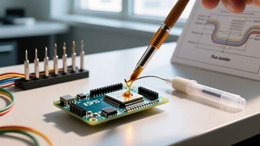
- SMD Rework: Use a syringe of no-clean tack flux like Amtech NC-559-V2-TF. Dispense a microscopic dot (approx. 1mm diameter) directly over the pad using a 22-gauge Luer-lock needle.
- Through-Hole & Wires: Use a liquid rosin flux like Kester 186 Mildly Activated Rosin. Apply with an acid brush, ensuring the flux coats the inside of the barrel and the component lead.
Step 3: Thermal Profiling and Solder Introduction
This is where most hobbyists fail. They touch the solder to the iron, melt it, and then transfer the molten blob to the fluxed pad. Do not do this. The flux will burn off the iron tip instantly, leaving you with oxidized solder.
- Place the pre-heated iron tip (set to 320°C for leaded, 360°C for SAC305 lead-free) directly onto the pad and component lead simultaneously.
- Hold for 1 to 2 seconds. You will see the external flux bubble and outgas. This is the activator chemically dissolving the oxides.
- Feed the solder wire into the pad, not the iron tip. Capillary action will instantly wick the molten solder into the fluxed joint.
- Remove the solder wire first, then the iron tip.
Expert Tip: If the flux stops bubbling and turns into a hard, dark amber crust before the solder flows, you have exceeded the flux's thermal dwell time. The activators have burned off, and the joint will suffer from dewetting. Remove the iron, add fresh flux, and try again.
Troubleshooting Common Flux Failures
Even with the right chemistry, improper application leads to distinct visual defects. Here is how to diagnose them based on the NASA Electronic Parts and Packaging (NEPP) workmanship guidelines.
1. Solder Balling and Splattering
Cause: Moisture trapped in water-soluble flux or applying too much liquid flux. When the iron hits the pool of liquid flux, the rapid phase change from liquid to gas causes micro-explosions, launching tiny spheres of molten solder across the PCB.
Solution: Allow liquid flux to dry for 10-15 seconds before applying heat, or switch to a high-viscosity gel/tack flux for SMD applications.
2. Charred, Blackened Residue
Cause: Iron temperature is too high, or the tip was held on the joint for longer than 4 seconds. The rosin base has carbonized.
Solution: Lower the station temperature by 20°C. Carbonized flux is highly acidic and can cause long-term electrochemical migration (dendritic growth) leading to short circuits. It must be scrubbed off with a specialized solvent like Techspray Ecoline and a hog-bristle brush.
3. Cold, Grainy Joints Despite Flux Presence
Cause: Insufficient thermal mass transfer. The flux did its job, but the pad never reached the solder's liquidus temperature (183°C for Sn63, 217°C for SAC305). The solder merely solidified on top of the flux layer rather than alloying with the copper.
Solution: Increase the iron tip width. A chisel tip (e.g., Hakko T18-D24) transfers heat vastly superior to a conical tip, ensuring the flux and the pad reach thermal equilibrium simultaneously.
Cleaning and IPC-A-610 Compliance
Understanding what flux is used for when soldering also requires knowing when to remove it. According to the SMTnet industry knowledge base and IPC-A-610 Class 3 (High-Reliability) standards, all water-soluble (OA) flux residues must be completely removed within 2 hours of soldering, as the organic acids will aggressively eat through copper traces. Use heated (60°C) deionized (DI) water and a soft brush for OA fluxes.
For No-Clean fluxes (like MG Chemicals 8341), the residue is designed to be left on the board. The activators are encapsulated in the synthetic resin upon cooling, rendering them inert. However, if the board requires conformal coating or underfill, the no-clean residue must be removed using a saponifier, as the resin will prevent the coating from adhering to the fiberglass substrate.
Summary Checklist for Perfect Flux Application
- Verify the flux chemistry matches your cleaning capability (No-Clean vs. Water-Soluble).
- Mechanically clean heavy oxidation before chemical flux application.
- Apply external tack flux for SMD; do not rely solely on wire cores.
- Heat the pad and lead first, allowing the flux to outgas and activate.
- Introduce solder to the workpiece, not the iron tip.
- Inspect for proper wetting (concave fillet, shiny finish for leaded, matte for lead-free).
Mastering flux application transforms soldering from a frustrating guessing game into a predictable, repeatable metallurgical process. By respecting the thermal limits of your activators and matching the chemistry to your specific assembly requirements, you will consistently produce joints that meet stringent aerospace and commercial reliability standards.