
The Stakes of Professional XLR Soldering
In the high-stakes environments of live touring, broadcast television, and permanent studio installations, a failed audio connection is unacceptable. While consumer audio relies on molded, disposable cables, the professional audio industry demands field-repairable, robust interconnects. Mastering XLR soldering is not just about joining metal; it is about ensuring signal integrity, managing electromagnetic interference (EMI), and building mechanical resilience that survives being run over by road cases and dragged across arena floors.
This guide dives deep into the exact methodologies, materials, and industry standards required to build and repair broadcast-grade XLR cables in 2026.
Anatomy of a Broadcast-Grade XLR Connection
The undisputed industry standard for professional XLR connectors is the Neutrik XX-Series (specifically the NC3MXX for male and NC3FXX for female). Switchcraft's 3FHD and 3MHD series are also prevalent in permanent installations, but Neutrik dominates the touring and broadcast sectors due to its proprietary chuck-type strain relief and enclosed silver-plated contacts.
Key Mechanical Features
- Chuck-Type Strain Relief: Unlike older clamp-style connectors that crush the cable jacket, the XX-series uses a polyamide chuck that grips the cable jacket radially, providing up to 220 N (50 lbs) of retention force without compromising the internal dielectric.
- Boot and Gland: A tapered polyurethane boot prevents the cable from kinking at the connector exit, a common failure point in dynamic stage environments.
- Grounding Ring: A separate metal ring ensures continuous shield grounding to the mating connector's shell, vital for EMI shielding in RF-heavy environments.
Industry Wiring Standards (AES & EBU)
The Audio Engineering Society (AES) and the European Broadcasting Union (EBU) strictly define the pinout for balanced analog audio. Deviating from this standard will result in phase cancellation and catastrophic hum when interfacing with standardized AES audio equipment.
| Pin Number | Function | Standard 3-Core Color | Star-Quad Color (e.g., Canare 4S11) |
|---|---|---|---|
| Pin 1 | Ground / Shield | Drain Wire / Bare | Drain Wire / Bare |
| Pin 2 | Hot (+ / Non-Inverting) | Red | White + White/Green (Twisted) |
| Pin 3 | Cold (- / Inverting) | Black / White | Blue + Blue/Green (Twisted) |
Note: Star-quad cable (four conductors twisted in a star pattern) offers 10 to 30 dB better rejection of electromagnetic interference than standard twisted pair, making it mandatory for runs near lighting dimmers or power distribution.
The 2026 Pro Audio Soldering Workbench
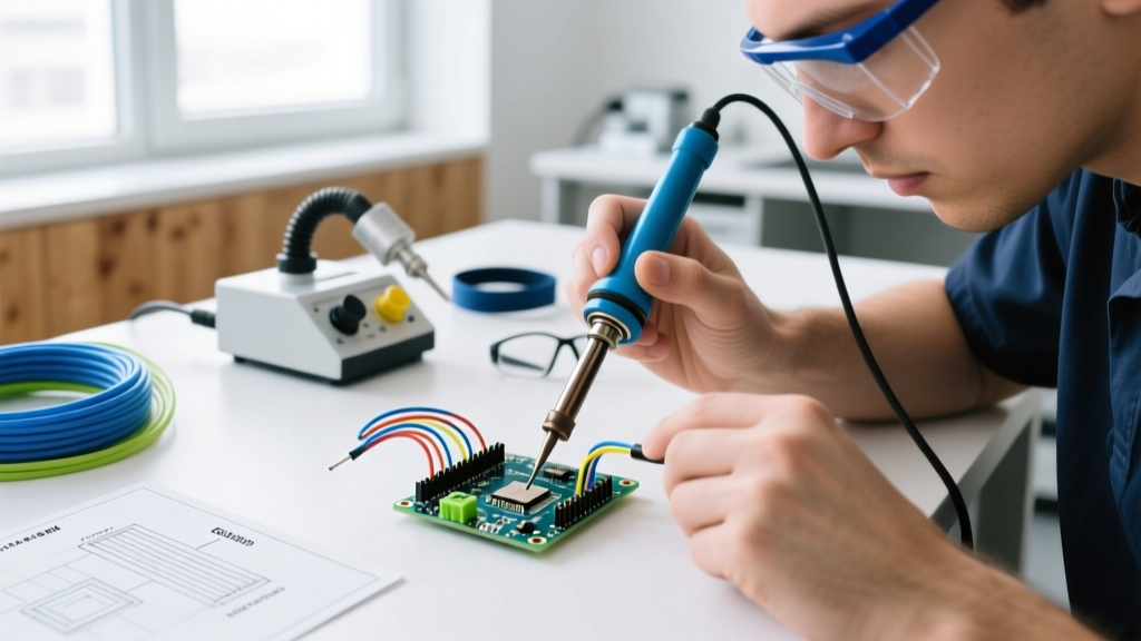
Building reliable XLR cables requires precise thermal control. Using a cheap, unregulated iron will burn the flux, oxidize the pad, and destroy the cable's internal polyethylene dielectric.
Essential Tools and Materials
- Soldering Station: Hakko FX-888D or Weller WES51. Set the temperature to 350°C (662°F) for standard leaded solder, or 380°C (716°F) for lead-free SAC305. (Expect to invest $115–$140 for a genuine station in 2026).
- Solder: Kester 44 (63/37 eutectic) rosin-core, 0.031" diameter. The eutectic ratio ensures an instant solid-to-liquid transition, preventing cold joints caused by micro-movements during the cooling phase.
- Flux: Amtech NC-559-V2-TF tacky flux in a syringe. Essential for reworking oxidized vintage XLR pins.
- Cable: Belden 1800F or Mogami W2549. Both feature conductive PVC inner shields to eliminate triboelectric noise (handling noise) when the cable is flexed.
- Heat Shrink: 3/32" for individual conductors, 1/4" for the main shield bundle.
Step-by-Step XLR Soldering Workflow
Speed and consistency are critical when building a 100-cable snake for a touring rig. Follow this exact sequence to ensure uniformity and reliability.
- Cable Preparation: Strip the outer jacket back exactly 1.5 inches. Do not nick the braided shield. Fold the shield back and twist it into a single pigtail. Strip the inner dielectric of the signal conductors by exactly 3/16".
- Tinning: Apply a small amount of solder to the exposed copper of the signal wires and the twisted shield. Tin the inside of the XLR connector pins (Pin 1, 2, and 3) simultaneously. The pre-tinning creates a metallurgical bond that drastically reduces the time the iron needs to be applied later.
- Heat Shrinking: Slide 3/32" heat shrink over the signal conductors. Do not use electrical tape; tape adhesive melts under stage heat and creates a conductive, messy sludge that can short Pin 2 to Pin 3.
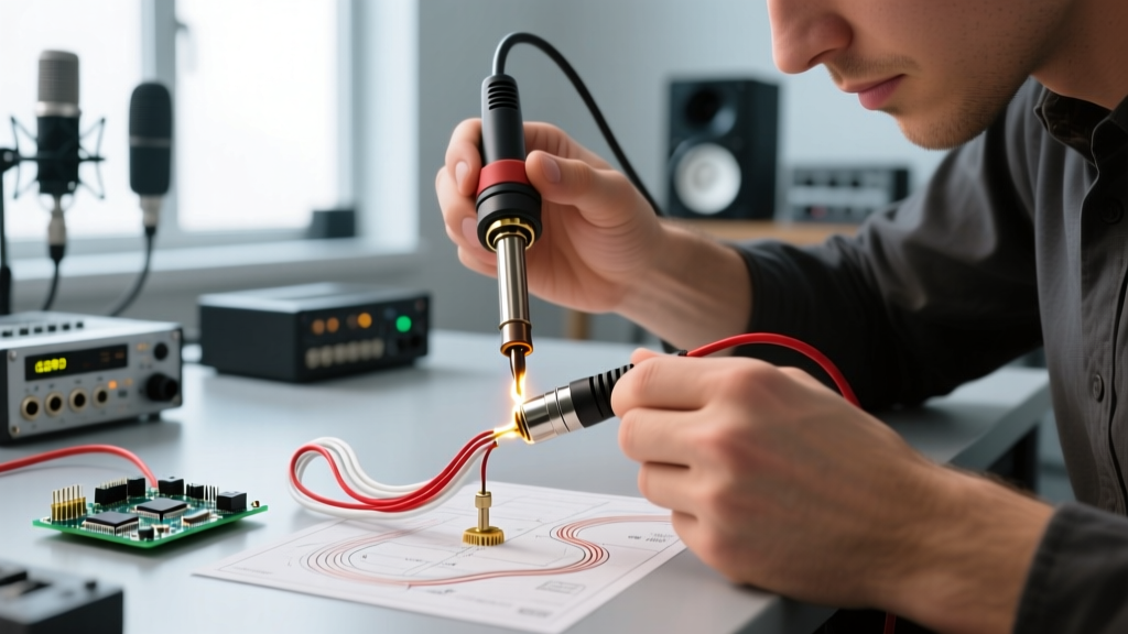
- The 3-Second Soldering Rule: Insert the wire into the solder cup. Apply the iron tip to the outside of the cup, not the wire. Count to three. The solder should flow smoothly into the cup via capillary action. Remove the iron and hold the wire perfectly still for two seconds until the solder crystallizes.
- Assembly and Strain Relief: Slide the heat shrink over the solder joints and apply heat. Thread the cable through the Neutrik boot, strain relief chuck, and rear housing. Tighten the chuck nut firmly—this radial compression is what prevents the solder joints from bearing any mechanical load.
The "Pin 1 Problem" and Shield Grounding
One of the most debated topics in audio engineering is how to handle the shield (Pin 1). Incorrect shield termination leads to ground loops, resulting in 60Hz/50Hz mains hum.
Industry Consensus: The shield (Pin 1) must be connected to the connector shell at both ends to maintain continuous EMI shielding. However, if a ground loop occurs, the solution is not to lift the audio ground (Pin 1) at the XLR connector. Lifting Pin 1 compromises the cable's RF shielding, turning it into an antenna. Instead, ground loops should be resolved using audio isolation transformers (e.g., Jensen ISO-Max) or by addressing the facility's AC power grounding topology.
Always ensure the shield is soldered cleanly to Pin 1 and that the Neutrik grounding ring makes firm contact with the mating chassis.
Soldered vs. Crimped XLR: An Industry Debate
While soldering remains the gold standard for custom and repairable cables, some high-volume manufacturers and broadcast trucks have adopted crimped XLR connections. Here is how they compare in real-world industry applications.
| Feature | Soldered XLR (Standard) | Crimped XLR (e.g., Hirschmann / Crimp Neutrik) |
|---|---|---|
| Tensile Strength | High (Dependent on strain relief chuck) | Very High (Cold-weld metallurgical bond) |
| Field Repairability | Excellent (Requires only iron and solder) | Poor (Requires specific, expensive ratcheting crimp tool) |
| Production Speed | Slow (3-5 minutes per connector) | Fast (45-60 seconds per connector) |
| Thermal Damage Risk | Moderate (Can melt dielectric if unskilled) | None (Cold process) |
| Best Use Case | Touring, Live Sound, Custom Studio Snakes | Pre-fabricated OEM cables, High-volume manufacturing |
For the independent audio technician, touring sound engineer, or studio owner, soldered XLR connections remain the superior choice. The ability to repair a severed snake channel in a dark backstage corridor with a portable butane iron (like the Portasol Pro 125) is a critical survival skill that crimped connectors simply cannot offer.
Final Quality Assurance: Testing the Connection
Never deploy a newly soldered XLR cable without testing. A visual inspection is insufficient. Use a dedicated cable tester (such as the Galaxy Audio CT-200 or the NTI Audio Minirator) to verify:
- Continuity: Pins 1-1, 2-2, and 3-3 are fully connected.
- Isolation: No shorts exist between Pin 1 and 2, Pin 2 and 3, or any pin and the outer shell (unless intentionally bonded via Pin 1).
- Phase/Rotation: Pin 2 is strictly Hot (+) at both ends. A reversed phase cable will cause severe low-frequency cancellation when summed with a correctly wired microphone.
By adhering to these stringent material choices, thermal profiles, and wiring standards, your XLR soldering will meet the rigorous demands of the professional audio industry, ensuring flawless signal transmission for years to come.