
The Hidden Complexity of Wire Soldering
While printed circuit board (PCB) assembly often dominates the electronics discourse, wire soldering remains the backbone of high-reliability systems. From aerospace harnesses to high-fidelity audio interconnects and high-current EV battery management systems, a poorly executed wire joint is the number one cause of field failure. It seems deceptively simple: strip, twist, tin, and heat. Yet, the metallurgical and mechanical realities of joining stranded copper to terminals or other wires require a rigorous, standardized approach.
To elevate your technique beyond hobbyist guesswork, we have synthesized insights from IPC-certified instructors, aerospace harness fabricators, and metallurgical engineers into this comprehensive expert roundup. Whether you are building a custom wiring harness or repairing a delicate thermocouple, these professional methodologies will ensure your connections survive vibration, thermal cycling, and high-current loads.
"A solder joint is only as strong as its weakest mechanical interface. If you compromise the copper strands during stripping, no amount of perfect soldering will save the wire from fatigue failure." — Senior Harness Engineer, Commercial Aerospace Sector
Expert 1: The Metallurgist on Alloy & Flux Selection
The foundation of any reliable wire joint is the solder alloy and flux chemistry. As we navigate the supply chain realities of 2026, sourcing consistent, high-quality wire solder requires understanding the exact phase diagrams of your materials.
Leaded (Sn63/Pb37) vs. Lead-Free (SAC305)
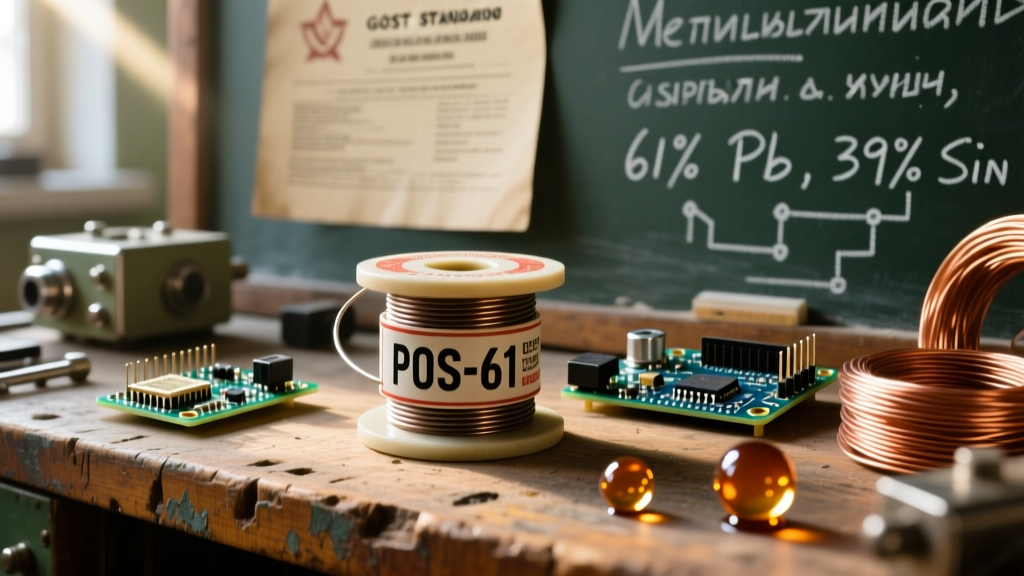
For Class 3 high-reliability and general prototyping, Sn63/Pb37 (Tin/Lead) remains the gold standard. It is a true eutectic alloy, meaning it transitions from liquid to solid instantly at 183°C (361°F). This eliminates the "pasty" or plastic phase where micro-movements can cause catastrophic cold joints.
Conversely, SAC305 (96.5% Sn, 3.0% Ag, 0.5% Cu) is the standard lead-free alternative. It melts between 217°C and 220°C. Because SAC305 has a higher surface tension and does not wet copper as aggressively as tin-lead, it requires higher iron temperatures (typically 350°C to 380°C) and more active fluxes to break down oxidation on stranded wire.
Flux Chemistry: Why ROL0 is Mandatory
Wire insulation traps heat and outgasses when burned. Using highly active acid fluxes can lead to long-term corrosion, especially in humid environments. Experts universally recommend ROL0 (Rosin, Low activity, 0% halides) flux for manual wire soldering. It provides sufficient oxide removal at soldering temperatures but remains completely inert and non-conductive at room temperature, eliminating the need for aggressive post-solder cleaning.
Expert 2: Aerospace Wire Preparation Standards
Wire preparation is where 80% of wire soldering defects are born. The goal is to expose the precise amount of copper without altering its mechanical geometry. According to the IPC-J-STD-001 Requirements for Soldered Electrical and Electronic Assemblies, any nick, scrape, or cut on a copper strand that reduces the individual strand diameter by more than 10% is a strict rejection criterion for high-reliability applications.
Thermal vs. Mechanical Stripping
For standard PVC or cross-linked polyethylene (XLPE) insulation, precision mechanical strippers are sufficient. However, for high-temperature fluoropolymer insulations like PTFE (Teflon) or Kapton, mechanical stripping often drags and stretches the insulation, or nicks the copper. Aerospace technicians utilize thermal wire strippers, which use heated blades to melt through the insulation cleanly, leaving the copper strands pristine and perfectly flush.
The Strip-Length Matrix
Exposing too much wire invites short circuits and solder wicking; exposing too little results in insufficient mechanical wrap. Below is the industry-standard matrix for calculating strip lengths and thermal profiles based on American Wire Gauge (AWG).
| Wire Gauge (AWG) | Strip Length (mm) | Iron Temp (Sn63/Pb37) | Max Dwell Time | Terminal Wrap |
|---|---|---|---|---|
| 18 AWG | 6.0 - 7.0 mm | 350°C (662°F) | 3.0 Seconds | 180° - 270° |
| 22 AWG | 5.0 - 6.0 mm | 340°C (644°F) | 2.5 Seconds | 180° - 270° |
| 26 AWG | 4.0 - 5.0 mm | 330°C (626°F) | 2.0 Seconds | 180° - 270° |
| 30 AWG | 3.0 - 4.0 mm | 320°C (608°F) | 1.5 Seconds | Full Wrap (360°) |
Expert 3: Thermal Management & Preventing Melt-Back
One of the most pervasive failures in wire soldering is insulation melt-back. When a soldering iron dwells on a wire for too long, the heat conducts down the copper strands, melting the insulation from the inside out. This not only looks unprofessional but exposes bare wire, creating a severe short-circuit hazard.
The Heat Sink Technique
To protect delicate insulation (especially on 28 AWG and smaller silicone or PVC wires), professionals use a mechanical heat sink. Clamping a pair of steel hemostats or a heavy aluminum alligator clip between the stripped section and the insulation creates a thermal break. The metal clamp absorbs the conductive heat, keeping the insulation safely below its glass transition temperature.
Pre-Tinning: The Golden Rule
Never attempt to solder a raw, untinned stranded wire directly to a terminal. The strands will splay, and the dwell time required to heat both the terminal and the wire simultaneously will destroy the insulation. Always pre-tin the wire first. Apply a small amount of solder to the stripped strands so they bind together into a single, solid conductor. The pre-tinned wire should show the natural color of the solder at the tip, with a slight taper, and absolutely no solder wicking under the insulation.
Solder Sleeves vs. Manual Splicing: A Buyer's Perspective
For inline wire splices, the industry has largely shifted toward SolderSleeves (originally developed by Raychem, now TE Connectivity). These are heat-shrinkable tubing segments with a pre-formed ring of solder and flux in the center, plus meltable sealing rings at the ends.
- Manual Soldering Splices: Requires a Western Union (lineman's) splice, manual soldering, and separate heat-shrink application. High skill ceiling, time-consuming, but requires only a basic iron.
- SolderSleeves: Requires a calibrated heat gun (e.g., Master HG-501) set to roughly 200°C-250°C. The technician slides the sleeve over the stripped, mated wires and applies heat. The solder ring melts, capillary action pulls it into the strands, and the sealing rings melt to create a waterproof environmental seal. Cost: Approx. $1.50 - $3.00 per sleeve, but reduces labor time by 70%.
Buyer's Guide: Precision Tools for Wire Soldering
To execute these techniques, your tooling must offer rapid thermal recovery and precise mechanical control. Here are the top-tier recommendations for 2026:
- Hakko FX-888D Digital Soldering Station ($115 - $130): The undisputed workhorse. Its T18 tips offer excellent thermal mass for 18 AWG wires, while the digital calibration ensures your 350°C setpoint is accurate, preventing accidental insulation scorching.
- Weller WE1010NA ($135 - $150): Features a slightly faster thermal recovery rate than the Hakko, making it ideal for rapid sequential soldering of large wire harnesses where the tip loses heat to heavy copper terminals.
- Jonard ST-550 Precision Wire Stripper ($45 - $55): Unlike cheap automatic strippers that crush strands, this manual precision stripper features adjustable micrometer screws to set the exact blade depth for AWG 20 through 30, guaranteeing zero copper nicks.
- Engineer PA-09 Micro Stripper ($35): The best compact option for fine-gauge wires (AWG 24-30) commonly used in drone builds and micro-electronics.
Troubleshooting Common Wire Soldering Defects
Defect 1: Solder Wicking Under Insulation
The Cause: Stripping the wire too long, using excessive flux, or holding the iron on the wire for too long, allowing capillary action to pull liquid solder under the jacket.
The Consequence: The wire loses its flexibility at the joint. In high-vibration environments, the stiff, solder-impregnated section acts as a stress concentrator, leading to copper fatigue and a snapped wire.
The Fix: Adhere strictly to the strip-length matrix. Apply heat only to the exposed copper, and remove the iron the moment the solder flows.
Defect 2: The "Cold" or "Disturbed" Joint
The Cause: Moving the wire before the solder has completely solidified, or failing to pre-tin the wire, resulting in a grainy, dull, and fractured solder fillet.
The Consequence: High electrical resistance, leading to localized heating (I²R losses) and eventual thermal runaway or voltage drop.
The Fix: Secure the wire mechanically (using a "helping hands" tool or jig) before applying the iron. Ensure the iron tip is clean and tinned to facilitate instant heat transfer.
Final Thoughts on High-Reliability Connections
Wire soldering is an exercise in thermal discipline and mechanical respect. By adhering to the guidelines set forth by organizations like the NASA Safety and Mission Assurance (SMA) and IPC, you transition from simply "making things stick" to engineering robust electrical pathways. Invest in precision stripping tools, respect the eutectic properties of your chosen alloy, and never compromise on wire preparation. Your connections will not only pass inspection—they will survive the harshest real-world conditions.
For further reading on advanced interconnection systems and space-grade wiring protocols, consult the NASA Electronic Parts and Packaging (NEPP) Program archives.