
The Core Dilemma: Thermal Mass vs. Joint Integrity
In the realm of electrical fabrication, the decision between welding and soldering is rarely about which method is universally 'better.' Instead, it is a strict physics problem governed by thermal mass, base metal sensitivity, and current-carrying requirements. While soldering relies on capillary action and a filler metal that melts below 450°C (840°F) without melting the base metals, welding (whether resistance spot welding or TIG) achieves coalescence by melting the base metals themselves.
Making the wrong choice can lead to catastrophic failure modes: thermal runaway in lithium-ion cells, high-resistance voltage drops in solar busbars, or brittle intermetallic compounds in high-vibration environments. This decision framework will guide you through the exact parameters, equipment costs, and industry standards required to choose the right joining method for your electrical project.
The Welding vs Soldering Decision Matrix
Before selecting your equipment, map your project to the matrix below. This comparison highlights the operational boundaries of the four primary electrical joining methods.
| Process | Peak Temperature | Base Metal Melted? | Primary Electrical Use Case | Typical Equipment Cost |
|---|---|---|---|---|
| Resistance Spot Welding | ~1,400°C (Localized) | Yes (at interface) | 18650/21700 Li-ion battery tabs | $150 - $400 |
| Soft Soldering | 180°C - 350°C | No | PCB terminations, wire-to-lug | $50 - $800 |
| Exothermic Welding | ~1,400°C+ | Yes (Fusion) | Grounding rods, heavy busbars | $150 - $300 (per mold) |
| TIG / Brazing | 600°C - 2,500°C | Yes (TIG) / No (Brazing) | Aluminum chassis, copper pipes | $800 - $2,500+ |
Scenario 1: Lithium-Ion Battery Pack Assembly
Why Resistance Spot Welding is Mandatory
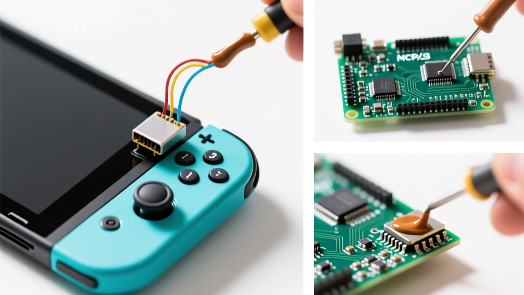
When building custom battery packs using cylindrical cells (18650, 21700, or 4680), resistance spot welding is the only acceptable method. Attempting to solder directly to the positive and negative terminals of a lithium-ion cell introduces severe safety hazards.
- The Thermal Runaway Risk: The internal Current Interrupt Device (CID) and plastic separator films inside a cell begin to degrade or melt at temperatures as low as 85°C to 130°C. A 100W soldering iron applied to a cell terminal will rapidly conduct heat inward, potentially venting toxic electrolytes or triggering thermal runaway.
- The Spot Welding Solution: A modern capacitive-discharge spot welder (like the Malectrics Kweld) delivers a massive pulse of current (often 1,000A to 1,500A) for a duration of just 10 to 50 milliseconds. This creates a localized fusion nugget between the nickel strip and the cell terminal without allowing time for the heat to propagate into the cell's internal chemistry.
Expert Specification: Always use 0.15mm thick, 10mm wide pure nickel strips for high-current battery packs. Nickel-plated steel strips are cheaper but possess higher electrical resistance, leading to dangerous voltage drops and heat generation under continuous 30A+ loads.
Scenario 2: High-Current Solar Busbars and Inverter Lugs
When to Solder vs. When to Exothermically Weld
For heavy-gauge wiring (4 AWG to 4/0 AWG) in solar arrays or EV inverter connections, the decision shifts from battery chemistry to thermal mass management.
The Limits of Soft Soldering Heavy Copper
Soldering a 4/0 AWG copper lug requires overcoming the immense thermal sink of the copper. A standard 60W or even 100W iron is useless here; the heat dissipates into the wire strands before the 60/40 tin-lead alloy can achieve proper wetting. According to the IPC J-STD-001 standards, a proper solder joint requires visible filleting and complete capillary penetration. To achieve this on heavy lugs, you need:
- A high-wattage iron (e.g., Weller WHA3000 at 300W) or a Sievert propane torch.
- Heavy-duty, non-corrosive flux to prevent oxidation at high temperatures.
- Pre-tinning of both the wire strands and the lug barrel before final joining.
The Exothermic Welding Alternative
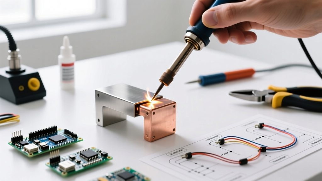
For permanent, high-vibration, or buried grounding connections (like attaching a 4/0 AWG bare copper wire to a ground rod), soft soldering is a failure point waiting to happen. Solder is susceptible to creep and galvanic corrosion in soil. Instead, use exothermic welding (commonly known by the brand name Cadweld). This process uses a chemical reaction between copper oxide and aluminum powder to generate molten copper at over 1,400°C, permanently fusing the wire to the rod in a molecular bond that outlasts the surrounding infrastructure.
Step-by-Step Decision Tree for DIY Fabricators
Use this rapid diagnostic flow to determine your joining methodology for any electrical component:
- Is the component sensitive to heat or internal pressure?
- Yes (e.g., Li-ion cells, capacitors, sensitive ICs): Use Resistance Spot Welding or low-temp conductive epoxies.
- No: Proceed to Step 2.
- Will the joint be buried, subjected to severe vibration, or carry >200A continuously in a structural capacity?
- Yes (e.g., Grounding grids, heavy busbars): Use Exothermic Welding or TIG welding.
- No: Proceed to Step 3.
- Is the joint wire-to-lug, PCB termination, or low-voltage signal?
- Yes: Use Soft Soldering (ensure iron wattage is matched to the copper thermal mass).
Troubleshooting Edge Cases and Failure Modes
Even when the correct process is selected, poor execution leads to specific failure modes. Here is how to diagnose them:
Edge Case 1: Spot Welds 'Popping' Off Under Tension
The Cause: This is almost always caused by using nickel-plated steel instead of pure nickel, or failing to clean the battery terminals. Steel has a higher resistance and requires different pulse timings. Furthermore, factory-applied anti-corrosion coatings on cell terminals act as an insulator. The Fix: Abrade the cell terminals lightly with a Scotch-Brite pad and wipe with 99% isopropyl alcohol. Calibrate your spot welder's pulse width using scrap cells of the exact same brand and model.
Edge Case 2: Crystalline or 'Cold' Solder Joints on Heavy Lugs
The Cause: A dull, grainy, or crystalline solder joint on a heavy copper lug indicates that the wire moved while the alloy was in its plastic (semi-solid) state, or the flux was exhausted before the solder flowed. This creates a high-resistance joint that will melt under load. The Fix: Never rely on rosin-core solder alone for heavy lugs. Apply external liquid or paste flux to the strands. Heat the lug and wire, not the solder wire itself. The solder should melt instantly upon contact with the copper, not from the iron's tip. As noted by the American Welding Society (AWS) guidelines on thermal joining, proper heat soak is critical for metallurgical bonding.
Industry Standards and Safety Guardrails
Professional electrical fabrication is governed by strict safety and quality standards. When designing joints for commercial or high-liability DIY applications (like home solar or marine DC systems), keep these benchmarks in mind:
- IPC J-STD-001: The global standard for soldered electrical assemblies. It dictates that solder must wet the surfaces and form a continuous fillet. 'Ball' or 'blob' joints where the solder sits on top of the wire without capillary action are classified as defects.
- UL 486A-486B: Standard for Wire Connectors. This dictates the mechanical and thermal cycling requirements for lugs. If you are soldering a lug, the solder must not wick entirely up the flexible wire strands, as this turns a flexible wire into a brittle, solid conductor that will snap under vibration.
- Battery Safety Limits: The National Renewable Energy Laboratory (NREL) extensively documents the thermal limits of lithium-ion cells. Keeping the outer casing temperature below 60°C during the joining process is critical to preventing micro-shorts and electrolyte degradation.
Final Verdict: Match the Tool to the Metallurgy
The welding vs soldering debate is ultimately resolved by looking at the metallurgy of your base materials and the thermal limits of the components attached to them. Soldering remains the undisputed king of PCB work, wire terminations, and low-stress electrical connections due to its low cost and precision. However, the moment you introduce high-current battery chemistries or structural grounding requirements, you must graduate to resistance or exothermic welding. Invest in the correct power supply, respect the thermal limits of your components, and always validate your joints with a milliohm meter before putting them into service.