
Introduction to XT90 Material Science
The Amass XT90 connector has become the undisputed standard for high-discharge DC applications, ranging from heavy-lift FPV drones and e-foils to DIY solar battery banks. Rated for 90A continuous and 120A burst current, the physical robustness of the XT90 is undeniable. However, the process of soldering XT90 connectors introduces a complex metallurgical and thermal challenge. Unlike standard low-current electronics, an XT90 joint must handle massive thermal cycling and high-current density without degrading. This material compatibility guide dissects the exact interactions between solder alloys, flux chemistries, wire insulations, and the base metals of the XT90 connector to ensure your high-amp joints survive the 2026 landscape of extreme RC and off-grid applications.
The Metallurgy of Amass XT90 Contacts
To achieve optimal wetting and mechanical strength, you must understand what you are soldering to. The male and female contacts of a genuine Amass XT90 are stamped from a high-conductivity copper alloy (often a brass or beryllium-copper blend for spring tension) and subsequently flash-plated with gold. This gold plating serves a dual purpose: it prevents oxidation during storage and ensures low contact resistance when mated. However, gold complicates the soldering process.
The Gold Embrittlement Phenomenon
When molten tin contacts gold, the gold rapidly dissolves into the solder pool, forming a brittle intermetallic compound (IMC) known as AuSn4. If the soldering iron is left on the joint too long, or if the solder volume is too small to dilute the gold concentration, this IMC layer thickens. A thick AuSn4 layer creates a mechanically fragile joint that can fracture under the physical stress of plugging and unplugging the connector. To mitigate this, you must use a soldering iron with high thermal recovery to complete the joint in under three seconds, minimizing the time gold is exposed to molten tin. For deeper insights into intermetallic formation, refer to the IPC J-STD-001 standards for soldered electrical assemblies.
Solder Alloy Compatibility Matrix
Choosing the right solder alloy is critical for high-current DC connectors. The alloy must exhibit excellent wetting on copper/brass, low electrical resistance, and high mechanical shear strength. Below is a compatibility matrix for the most common alloys used when soldering XT90 connectors.
| Alloy Designation | Composition | Melting Point | Wetting on XT90 | Verdict for XT90 |
|---|---|---|---|---|
| Sn63/Pb37 | 63% Tin, 37% Lead | 183°C (Eutectic) | Excellent | Best Overall. Eutectic phase means no plastic state, reducing cold joint risk during cooling. |
| Sn60/Pb40 | 60% Tin, 40% Lead | 183°C - 190°C | Very Good | Good. Slight plastic phase requires holding the joint perfectly still while cooling. |
| SAC305 | 96.5% Sn, 3% Ag, 0.5% Cu | 217°C - 220°C | Good (Requires more heat) | Use with caution. Higher melting point risks melting the PA66 nylon housing if iron wattage is insufficient. |
| Sn99.3/Cu0.7 | 99.3% Tin, 0.7% Copper | 227°C | Fair | Avoid. High melting point and poor wetting on heavy gauge wires make this unsuitable for hobbyist XT90 work. |
For 95% of DIY and professional RC builders, Sn63/Pb37 (63/37) remains the superior choice in 2026. Its lower melting point reduces thermal stress on the nylon connector housing, and its eutectic nature guarantees a reliable transition from liquid to solid.
Flux Chemistry: What to Use and What to Avoid
Flux is the chemical engine that drives solder wetting. However, the enclosed, cup-like geometry of the XT90 female connector and the deep barrel of the male connector make post-soldering cleaning nearly impossible. This physical constraint dictates your flux selection.
- Rosin Mildly Activated (RMA): The gold standard for XT90s. Fluxes like Kester 186 or standard rosin-core solder leave a hard, non-conductive, non-corrosive residue that safely remains inside the connector housing.
- No-Clean (NC): Acceptable and widely used. Modern no-clean fluxes (like Amtech NC-559) leave a minimal, clear residue. Ensure you use a high-quality brand, as cheap no-clean fluxes can become slightly conductive under high humidity and high DC voltage.
- Water-Soluble (OA): STRICTLY AVOID. Water-soluble fluxes are highly acidic and must be thoroughly washed off with deionized water. Because you cannot effectively flush the inside of an XT90 nylon housing, trapped OA flux will cause rapid galvanic corrosion, eventually eating through the copper strands and causing a high-resistance, heat-generating failure point.
Critical Warning: Never use plumbing paste flux or acid-core solder on XT90 connectors. The aggressive chlorides will destroy the copper wire strands within months, leading to catastrophic high-amp failure. Always use electronics-grade rosin or no-clean flux, as detailed in Adafruit's comprehensive soldering guide.
Wire Insulation Compatibility: Silicone vs. PVC
The material compatibility extends beyond the metal joint to the wire insulation. When soldering XT90 connectors, you are typically working with 8 AWG or 10 AWG wire. The insulation material must withstand the intense localized heat required to bring a massive copper contact up to 183°C+.
Why Silicone Wire is Mandatory
High-strand-count silicone wire (typically 1000+ strands of 0.08mm copper for 8 AWG) is the only appropriate choice. The silicone jacket (polydimethylsiloxane) can withstand continuous temperatures up to 200°C and peak soldering temperatures well over 300°C without melting or shrinking back. Conversely, standard PVC insulation begins to soften at 80°C and melts completely around 105°C. If you attempt to solder an XT90 to PVC wire, the insulation will melt back, exposing bare strands that can short against the connector housing or wick solder deep into the flexible wire, creating a stiff, brittle stress point that will eventually snap under vibration.
Thermal Management: Tooling and Technique
The most common failure mode when soldering XT90 connectors is a "cold joint" caused by an underpowered soldering iron. An 8 AWG copper wire and a thick brass XT90 contact act as massive heat sinks. A standard 40W hobby iron will simply dump its heat into the metal, failing to reach the solder's melting point, while the operator applies excessive dwell time, eventually melting the surrounding PA66 nylon housing.
Recommended Soldering Irons for High-Mass Joints
To achieve a three-second solder joint, you need an iron with high wattage and excellent thermal recovery. Here are the top-tier tools for the job in 2026:
- Pine64 Pinecil V2 ($26): A RISC-V powered portable iron. When paired with a 24V power supply (like a 65W PD laptop charger), it pushes enough thermal mass to handle 10 AWG XT90 joints effortlessly. Use a TS-B2 (bevel) tip for maximum surface contact.
- Hakko FX-951 ($230): The professional bench standard. Its 70W cartridge system provides near-instant thermal recovery. Equip it with an Hakko T15-D24 (heavy chisel) tip.
- Weller WE1010 ($120): A solid mid-range 70W station. Use the Weller ETA (chisel) tip. Avoid conical (pointed) tips entirely; they lack the surface area required to transfer heat into heavy-gauge wire.
Step-by-Step Soldering Protocol
Follow this exact sequence to ensure perfect material integration and mechanical strength:
- Preparation: Strip exactly 7mm of silicone insulation from the 8 AWG or 10 AWG wire. Apply a small amount of liquid RMA flux to the exposed strands.
- Tin the Wire: Heat the wire with your bevel or chisel tip and feed 63/37 solder until the strands are fully saturated. The wire should look shiny and uniform, with no dry strands.
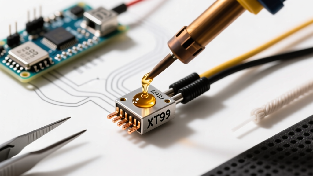
- Tin the Connector: Hold the XT90 contact in a helping-hands fixture (never hold it with your fingers; the thermal transfer will burn you). Flux the inside of the solder cup. Apply the iron to the outside of the cup and feed solder until the cup is roughly 50% full.
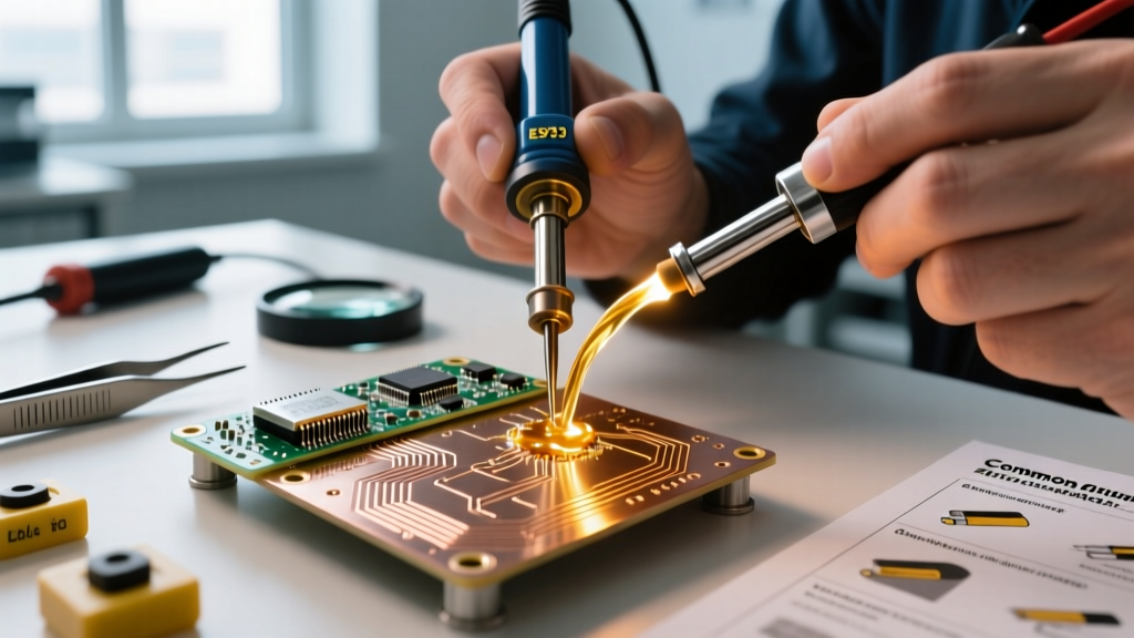
- The Mate: Re-tin the tip of your iron. Place the iron against the outside of the XT90 cup to re-melt the solder pool. Insert the pre-tinned wire straight into the cup. Hold perfectly still for 3 seconds until the solder solidifies into a dull, frosty finish.
- Insulation: Slide a piece of 3:1 ratio, dual-wall adhesive-lined heat shrink over the joint. Apply heat until the shrink tightens and the inner adhesive melts out of the ends, creating a waterproof, strain-relieved seal.
Troubleshooting Common XT90 Failure Modes
Even with the right materials, technique errors can compromise the joint. Here is how to identify and fix common issues:
- Wicking into the Strands: If solder wicks too far up the wire past the connector cup, the wire loses its flexibility. Fix: Reduce your wire strip length to 5mm and ensure your iron is not overheated (keep it around 350°C for 63/37 solder).
- Melted Nylon Housing: If the black or yellow PA66 plastic deforms, you applied heat for too long or used an iron that was too cool, forcing you to hold it in place for 10+ seconds. Fix: Upgrade to a higher wattage iron or a larger chisel tip to transfer heat faster.
- Dull, Grainy Joint: This indicates a disturbed joint (moved while in the plastic phase) or the use of lead-free solder that wasn't heated sufficiently. Fix: Re-flux the joint, reheat with a clean, tinned tip, and hold the wire completely immobilized until the solder cools below 150°C.
By respecting the material science behind the components—matching the correct eutectic alloy with rosin flux, high-temp silicone wire, and high-thermal-mass tooling—your XT90 connectors will deliver flawless, low-resistance power delivery for years of high-amp operation.