
The Genesis: Thermal Lag and Lifted Pads (1970s–1980s)
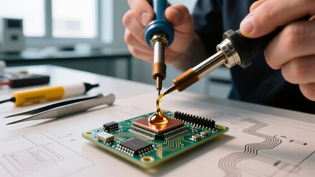
Before the miniaturization of consumer electronics, through-hole components dominated PCB assembly. However, as early surface-mount devices (SMDs) began appearing in aerospace and medical electronics in the late 1970s, technicians faced a critical problem: how to simultaneously heat two pads of a fragile MELF diode or early SOIC chip without applying mechanical stress. The earliest iterations of soldering tweezers were essentially two modified soldering irons strapped together, sharing a single, poorly regulated heating element.
These first-generation tools suffered from severe thermal lag. Technicians had to set the base station to dangerously high temperatures (often exceeding 400°C) to compensate for the thermal mass of the copper tips and the heat sinking of the PCB. The result was a high incidence of 'pad lift'—where the FR-4 substrate's copper foil delaminated due to prolonged, uneven heat exposure. Furthermore, the tips lacked independent temperature control, meaning the tweezer arms often operated at different temperatures, leading to asymmetrical reflow and the dreaded 'tombstoning' effect on passive components.
The Ceramic Catalyst: Closed-Loop Feedback (1990s–2000s)
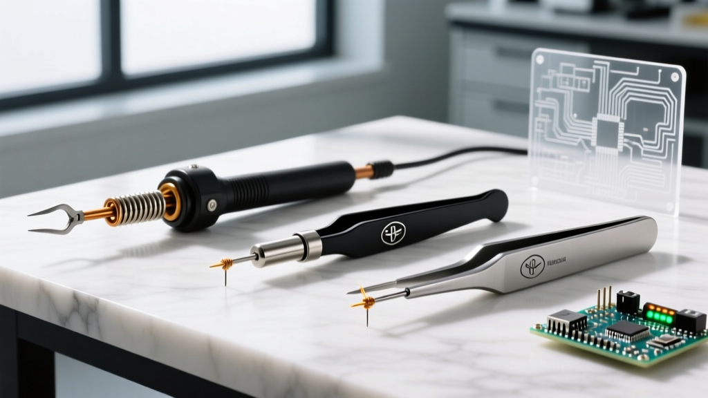
The true evolution of soldering tweezers began in the 1990s with the widespread adoption of ceramic heating elements and Curie-point magnetic temperature regulation. Companies like Weller and Hakko introduced dedicated thermal tweezer handpieces that plugged into standard digital stations. By embedding a thermocouple directly near the tip apex, these systems achieved closed-loop feedback.
During this era, the industry standard shifted toward lead-free alloys (like SAC305), which required higher reflow temperatures (217°C to 220°C) and tighter thermal profiles. The introduction of alumina ceramic heaters allowed soldering tweezers to recover their thermal setpoint in under three seconds. According to the NASA Workmanship Standards for electronic assembly, precise thermal profiling is critical to avoid intermetallic compound (IMC) overgrowth, which makes solder joints brittle. The ceramic-heated soldering tweezers of the 2000s finally allowed technicians to meet these stringent aerospace and military rework specifications without scorching adjacent components.
Pulse-Heat Thermodes: Solving the Ground Plane Problem
As we moved into the 2010s and beyond, component density exploded. The rise of 0201 and 01005 passives, alongside complex QFN and BGA packages, pushed constant-heat soldering tweezers to their absolute limits. The primary failure mode emerged when reworking components tied to heavy internal ground planes or thick copper pours (e.g., 4oz to 6oz copper in power electronics). An 80W constant-heat tweezer simply could not supply joules fast enough to overcome the thermal dissipation of a multi-layer ground plane, resulting in 'cold lap' joints.
This limitation birthed the modern pulse-heat (hot bar) soldering tweezer. Unlike constant-heat tools that maintain a steady 350°C, pulse-heat thermodes deliver a massive, controlled surge of current (often exceeding 1000W for a fraction of a second) directly through a high-resistance molybdenum or titanium thermode. This rapidly spikes the localized temperature to reflow, then immediately drops to prevent board delamination. Modern pulse systems utilize real-time resistance monitoring to determine the exact moment the solder liquefies, automatically cutting the power. This level of precision is heavily referenced in the IPC-7711/7721 Rework Standard for advanced SMD and flex-circuit modifications.
Constant Heat vs. Pulse Heat: 2026 Buyer’s Matrix
For lab managers and procurement officers outfitting a modern electronics repair facility in 2026, choosing between constant-heat and pulse-heat soldering tweezers requires a clear understanding of your specific rework volume and PCB complexity.
| Technology | Example Model (2026) | Approx. Price Range | Best Application | Primary Failure Mode / Edge Case |
|---|---|---|---|---|
| Constant Heat (Ceramic) | Weller WT2H with WTHA1 Handpiece | $450 – $600 (Station + Handpiece) | General SMD rework, 0402 to SOIC, standard 2-layer to 4-layer PCBs. | Insufficient thermal recovery on heavy ground planes; tip oxidation if left idle at 380°C. |
| Pulse-Heat (Hot Bar) | Apollo PA-2000 Series / Hughes Pulse Systems | $3,500 – $8,000+ | Flex circuits, heavy copper pours, FPC-to-PCB bonding, heat-sensitive substrates. | Thermode misalignment causing uneven pressure; requires strict planarity calibration. |
| Micro-Flame / Hot Gas Hybrid | JBC JTSE / Pace STK-Hot Air Tweezers | $800 – $1,200 | Desoldering large multi-pin connectors where physical contact might damage fragile pins. | Collateral heat damage to adjacent plastic connectors or sensitive ICs without Kapton shielding. |
Edge Cases and Failure Modes in Modern SMD Rework
Even with the advanced Weller WT Line or high-end JBC nano-tweezers, operator error and material incompatibilities remain the leading causes of rework failure. Understanding these edge cases is what separates a novice from a master technician.
- Flux Incompatibility at High Temps: Modern no-clean fluxes often contain halogen activators. When using soldering tweezers set above 360°C for lead-free rework, these activators can aggressively corrode the iron plating on the tweezer tips, leading to pitting and de-wetting within just a few hours of use. Always use rosin-based (RMA) flux for high-temperature tweezer rework to preserve tip life.
- The 'Wicking' Phenomenon on 0201s: When reworking 0201 resistors (measuring just 0.6mm x 0.3mm), the thermal mass of the tweezer tips can cause the solder to rapidly wick up the component terminations and onto the tweezer tips themselves, leaving a starved, weak joint on the PCB pad. The solution is to use ultra-fine, beveled tips (e.g., 0.3mm width) and apply a high-viscosity tacky flux to hold the component in place and localize the surface tension.
- Thermode Planarity in Pulse Systems: In pulse-heat soldering, if the thermode is not perfectly parallel to the PCB surface (within 0.05mm tolerance), one side of the component will reflow before the other. This creates a 'drawbridge' effect, pulling the component out of alignment as the solder's surface tension equalizes.
Expert Insight: 'The biggest mistake I see in 2026 repair labs is technicians using brass wool to clean pulse-heat molybdenum thermodes. Brass is softer than the thermode plating but hard enough to create micro-scratches where solder will permanently alloy and build up. Always use a specialized high-temp thermode cleaning stone or a damp cellulose sponge with a mild abrasive compound designed specifically for hot bar rework.' — Senior Rework Engineer, Aerospace Avionics Division.
Actionable Procurement Guide for Electronics Labs
If you are specifying soldering tweezers for a production or repair environment, follow this decision framework to ensure your capital expenditure aligns with your operational needs:
- Audit Your Board Stackups: If 80% of your rework involves standard 1.6mm FR-4 boards with 1oz copper and components no larger than QFP-100, a high-quality constant-heat ceramic system (like the Hakko FX-951 with a tweezer adapter or Weller WT2H) is sufficient. Budget approximately $150 annually per station for replacement WTH or T15-series tips.
- Evaluate Flex and Heavy Copper Needs: If your lab services automotive ECUs, LED lighting modules with metal-core PCBs (MCPCBs), or medical flex circuits, you must invest in a pulse-heat system. The upfront cost is high, but the reduction in scrapped boards due to delamination will yield an ROI within 14 months.
- Standardize Tip Geometries: Do not buy generic 'assortment' tip kits. Analyze your most common component footprints. For modern consumer electronics, stock heavily on 0.5mm and 0.8mm flat blade tips for 0402 and 0603 passives, and 1.5mm concave tips for SOIC and SOT-23 transistors. Concave tips cradle the component leads, preventing the tweezers from slipping and shorting adjacent pins.
- Implement Strict Calibration Schedules: Modern digital stations drift over time. Establish a bi-annual calibration protocol using a K-type thermocouple and a high-accuracy digital thermometer to verify that the temperature displayed on the station matches the actual tip temperature within ±3°C, a requirement for ISO 9001 and IPC-A-610 compliance.
The evolution of soldering tweezers from crude, pad-lifting clamps to highly calibrated, micro-processor-controlled thermal instruments mirrors the broader trajectory of the electronics industry. By understanding the physics of heat transfer and the historical limitations of older tools, modern technicians can leverage today's advanced equipment to achieve flawless, reliable SMD rework every time.