
The Metallurgy of Heat: Tracing the Soldering Temp Chart
For decades, the soldering temp chart was a relatively static document hanging in electronics manufacturing facilities. It dictated a simple rule: set the iron to 350°C, use 63/37 tin-lead solder, and trust the eutectic transition. However, the evolution of environmental regulations, component miniaturization, and advanced metallurgy has completely rewritten these guidelines. Today, a modern soldering temp chart is a complex matrix of alloy compositions, thermal mass considerations, and flux activation thresholds.
Understanding how we arrived at the 2026 standards for thermal profiling is not just an exercise in history; it is critical for avoiding tombstoning, pad lifting, and cold joints on modern high-density interconnect (HDI) printed circuit boards. Let us trace the evolution of soldering temperatures from the golden era of tin-lead to the complex nano-alloys of today.
The Pre-2006 Baseline: Tin-Lead and the Original Soldering Temp Chart
Before the mid-2000s, the electronics industry relied almost exclusively on Tin-Lead (SnPb) alloys. The undisputed king was Sn63/Pb37, a eutectic alloy that transitions from solid to liquid at a precise 183°C (361°F). Because it lacked a 'pasty' or plastic range, it solidified instantly, minimizing the risk of component shift or cold joints caused by micro-movements during cooling.
The historical soldering temp chart for this era was straightforward:
- Alloy Melting Point: 183°C
- Standard Iron Temperature: 315°C to 350°C (600°F - 662°F)
- Flux Activation: Rosin-based (R, RMA) activating around 200°C
Engineers utilized high-wattage irons with massive copper tips to deliver rapid thermal transfer. The primary concern was not thermal damage to the component, but rather ensuring the flux had sufficient time and heat to clean the oxidation from the copper pads before the solder wetted the surface.
The 2006 RoHS Paradigm Shift: Enter SAC305
The European Union's Restriction of Hazardous Substances (RoHS) Directive, fully enforced in 2006, banned lead in consumer electronics. This forced the industry to adopt lead-free alternatives, fundamentally breaking the old soldering temp chart. The EU RoHS Directive catalyzed the adoption of SAC305 (96.5% Tin, 3.0% Silver, 0.5% Copper).
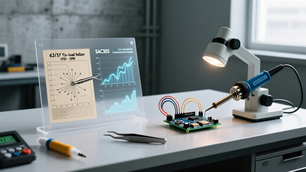
SAC305 introduced severe thermal challenges. Unlike Sn63/Pb37, SAC305 is non-eutectic. It has a solidus of 217°C and a liquidus of 220°C, creating a 3°C pasty range. More importantly, its higher melting point required soldering irons to be cranked up to 380°C - 400°C to achieve proper wetting.
Comparative Data: The Evolution of Standard Alloys
| Alloy Composition | Common Name | Melting Point (Solidus/Liquidus) | Recommended Iron Temp | Era of Dominance |
|---|---|---|---|---|
| Sn63/Pb37 | Eutectic Tin-Lead | 183°C / 183°C | 315°C - 350°C | 1960s - 2006 |
| Sn96.5/Ag3.0/Cu0.5 | SAC305 | 217°C / 220°C | 350°C - 380°C | 2006 - Present |
| Sn42/Bi58 | Bismuth-Tin | 138°C / 138°C | 250°C - 280°C | 2018 - Present (Niche) |
| Sn95/Sb5 | High-Temp Lead-Free | 232°C / 240°C | 380°C - 410°C | Aerospace/Automotive |
Codifying the Heat: IPC Standards and Thermal Profiling
As lead-free soldering caused widespread reliability issues in the late 2000s—such as thermal shock cracking in multilayer ceramic capacitors (MLCCs)—the industry needed standardized guidelines. The IPC-J-STD-001 standard became the bible for soldered electrical and electronic assemblies, dictating strict thermal excursion limits.
The modern soldering temp chart is no longer just about the iron's set temperature; it is about the thermal profile of the joint. IPC guidelines emphasize that the time a component spends above its maximum rated temperature (often 245°C for plastic-bodied ICs) must be strictly minimized. This led to the widespread adoption of active pre-heating. By bringing the entire PCB up to 100°C–120°C from the bottom before applying top-side iron heat, technicians reduce the delta-T (temperature difference), preventing pad delamination and allowing the iron to be set lower (e.g., 340°C instead of 380°C) while still achieving reflow.
Expert Insight: A common failure mode in 2026 rework stations is relying solely on the iron's digital readout. A station set to 360°C may drop to 280°C at the tip when it contacts a heavy ground plane. Modern soldering temp charts require you to factor in the thermal mass of the PCB and select tip geometries (like a bevel or hoof tip) that maximize surface contact area, rather than simply turning up the dial and risking flux burnout.
The 2026 Landscape: Low-Temp Bismuth and Nano-Alloys
The push for energy efficiency and the protection of ultra-sensitive RF and flexible circuits has driven the latest evolution in the soldering temp chart: low-temperature alloys. The most prominent is Sn42/Bi58 (Tin-Bismuth), which melts at a highly eutectic 138°C.
While Bismuth alloys drastically reduce thermal stress on components and prevent warping in large BGA packages, they introduce mechanical brittleness. To counter this, modern 2026 formulations often include trace amounts of silver or utilize specialized nano-core fluxes that leave a highly cross-linked, structural resin shell around the joint. When using Sn42/Bi58, the soldering temp chart dictates an iron temperature of just 250°C to 280°C. Exceeding 300°C with Bismuth can cause rapid oxidation and severe wetting failures.
Real-World Rework: Applying the Chart to Modern PCBs
When approaching a mixed-technology board in a modern lab, follow this actionable workflow based on current thermal guidelines:
- Identify the Alloy: Use an XRF analyzer or check the BOM. Never assume SAC305; mixing lead-free and tin-lead creates a low-melting ternary eutectic that will fail under thermal cycling.
- Pre-heat the Board: Use a bottom-side IR or convection pre-heater to reach 100°C. This is mandatory for SAC305 on boards with internal copper pours exceeding 2oz.
- Select the Station and Tip: For SAC305, use a high-thermal-recovery station like the JBC CD-2BQE or Weller WXD2. Select a chisel tip (e.g., Weller RT1) that matches the pad width to ensure instantaneous heat transfer.
- Monitor Dwell Time: Apply the iron for no more than 3 to 5 seconds per joint. If the solder does not flow, remove the iron, add fresh flux (ROL0 or ROL1 type), and reapply. Never 'scrub' the pad with a dry iron.
FAQ: Soldering Temperature Nuances
Why does my SAC305 solder joint look grainy and dull?
A dull, grainy appearance in SAC305 is often mistaken for a cold joint, but it is actually a characteristic of the alloy's crystalline structure as it cools through its pasty range. Unlike the shiny finish of 63/37 tin-lead, SAC305 naturally forms a matte, textured surface. According to SMTA guidelines, as long as the solder has properly wetted the pad and lead (forming a distinct meniscus), the joint is mechanically sound.
Can I use a single temperature for all components on a board?
No. A modern soldering temp chart is component-specific. A massive DPAK voltage regulator soldered to a ground plane requires a high-mass hoof tip at 380°C, while a nearby 0402 decoupling capacitor requires a micro-conical tip (like the JBC C115-112) at 320°C to prevent the solder from wicking up the lead and leaving a starved joint.
How do I calibrate my iron to match the chart?
Digital readouts on soldering stations drift over time due to thermocouple degradation in the heater cartridge. Use a calibrated tip thermometer (such as the Hakko FG-100) to measure the actual surface temperature of the tip under a slight load. Adjust the station's offset calibration to ensure the physical tip temperature matches your target soldering temp chart within ±5°C.
Conclusion
The soldering temp chart has evolved from a simple reference for tin-lead plumbing and basic electronics into a sophisticated thermal management tool. By understanding the historical shift from eutectic lead to non-eutectic SAC305, and now to specialized bismuth alloys, technicians and engineers can make informed decisions that ensure long-term reliability. In 2026, successful soldering is less about raw heat and more about precise thermal delivery, flux chemistry, and strict adherence to modern metallurgical standards.