
The Metallurgy of the Joint: Beyond Melting Metal
Learning how to use a soldering iron properly is fundamentally an exercise in applied metallurgy, not just heat application. When we convened a panel of IPC-certified soldering instructors and veteran aerospace electronics engineers for this 2026 roundup, the consensus was clear: most hobbyists and junior technicians treat soldering as a mechanical gluing process. In reality, you are engineering an intermetallic compound (IMC).
When molten solder (typically a tin-based alloy) contacts a copper pad, a metallurgical reaction occurs, forming Cu6Sn5 and Cu3Sn crystalline structures. According to the IPC J-STD-001 standards for soldered electrical and electronic assemblies, an ideal IMC layer is between 1 and 3 microns thick. Too little heat or time results in a weak, high-resistance mechanical bond (a cold joint). Excessive heat or prolonged dwell time causes the IMC layer to grow too thick, making the joint brittle and prone to micro-fracturing under thermal cycling.
Expert Insight: "The iron doesn't melt the solder onto the pad. The iron heats the pad and the component lead. The pad melts the solder. If you are feeding solder directly onto the iron tip and wiping it onto the joint, you are creating a cold joint masked by a rosin shell." — Master IPC Instructor, Aerospace Avionics Division
Thermal Profiling Matrix: Matching Alloy to Temperature
A common failure point when figuring out how to use a soldering station is relying on a single, static temperature setting. In 2026, with the market split between traditional leaded alloys for hobbyist/repair work and strict lead-free requirements for commercial production, dynamic thermal profiling is mandatory.
| Alloy Composition | Melting Point | Recommended Iron Setpoint | Max Dwell Time | Primary Use Case |
|---|---|---|---|---|
| Sn63/Pb37 (Eutectic) | 183°C (361°F) | 315°C - 340°C (600°F - 645°F) | 2 - 4 Seconds | Prototyping, repair, hobbyist |
| SAC305 (Sn96.5/Ag3.0/Cu0.5) | 217°C - 220°C (422°F - 428°F) | 350°C - 380°C (660°F - 715°F) | 3 - 5 Seconds | Commercial, RoHS-compliant PCBs |
| Sn42/Bi57 (Bismuth) | 138°C (280°F) | 220°C - 250°C (428°F - 482°F) | 2 - 3 Seconds | Low-temp rework, heat-sensitive ICs |
Note: Always increase your setpoint by 15°C - 20°C when working on heavy ground planes, as the copper acts as a massive heatsink, pulling thermal energy away from the joint.
Tip Geometry: The Conical Trap
Ask any novice how to use a soldering iron, and they will likely point to a fine conical tip, assuming a sharper point equals more precision. Our expert panel universally condemns conical tips for general through-hole and SMD work. A conical tip has a microscopic surface area at its apex, resulting in terrible thermal transfer and rapid oxidation.
The Expert-Approved Tip Roster
- Chisel (D-SIZE / 2.4mm): The undisputed workhorse. The flat edge maximizes surface area contact with both the pad and the lead simultaneously, ensuring equal heat distribution.
- Bevel / Hoof (B-SIZE): Ideal for drag-soldering fine-pitch SOIC and QFP integrated circuits. The concave scoop holds a small reservoir of molten solder and flux, allowing surface tension to pull the solder evenly across pins.
- Knife (K-SIZE): Excellent for navigating tight spaces and cleaning up 0402 or 0201 SMD pads where a standard chisel might bridge adjacent components.
For a deep dive into matching your tip to your thermal mass requirements, the Hakko Soldering Tip Selection Guide remains the industry's most comprehensive visual reference.
The 5-Step Execution Protocol
To achieve a Class 3 (High-Performance) solder joint as defined by NASA Workmanship Standards (NASA-STD-8739.3), follow this strict chronological sequence:
- Prep & Clean: Wipe the tip on damp cellulose sponge or brass wool. Apply a micro-layer of fresh solder to the tip (tinning) to prevent oxidation and create a thermal bridge.
- Apply Flux (If needed): For rework or lead-free boards, apply additional liquid or gel flux to the joint before applying heat. Flux lowers surface tension and removes oxides.
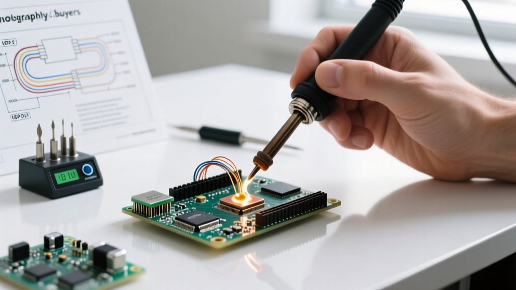
- Heat the Mass: Place the flat of the chisel tip so it touches both the PCB pad and the component lead simultaneously. Hold for 1 second.
- Feed the Solder: Introduce the solder wire to the joint, not the iron tip. Once the flux activates (bubbles slightly) and the solder flows smoothly like liquid mercury, stop feeding.
- The Exit Strategy: Remove the solder wire first, then swiftly sweep the iron away at a 45-degree angle. Hold the component perfectly still for 3 seconds while the joint transitions from liquid to solid (the plastic phase).
Flux Chemistry: The Unsung Hero
You cannot master how to use a soldering setup without mastering flux. In 2026, flux formulations are highly specialized:
- Rosin Mildly Activated (RMA): The standard for general electronics. Leaves a hard, amber residue that is non-corrosive but can be cleaned with isopropyl alcohol (IPA) for aesthetic or inspection purposes.
- No-Clean (NC): Synthetic resins that leave a clear, inert residue. Warning: Do not clean no-clean flux with IPA; it turns the residue into a white, corrosive sludge that can cause dendritic growth and short circuits over time.
- Water-Soluble (OA): Highly active organic acids used for heavily oxidized boards or large ground planes. Mandatory to clean with distilled water post-soldering, or it will aggressively eat the copper traces.
2026 Expert-Approved Hardware Recommendations
The market has shifted heavily toward direct-drive and high-recovery smart stations. Here is what the experts are using on their benches today:
| Model | Technology | Price Range (2026) | Expert Verdict |
|---|---|---|---|
| Pine64 Pinecil V2 | RISC-V, Direct USB-C PD | $26 - $32 | Unbeatable for portability and field repair. Heats to 300°C in 6 seconds. Requires a 65W+ PD power supply. |
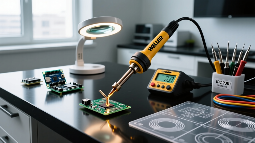
| Weller WE1010NA | 70W Ceramic Element | $115 - $130 | The modern bench standard. Excellent thermal recovery for mid-sized through-hole and SMD work. |
| Hakko FX-951 | 70W Cartridge (Tip + Element) | $280 - $310 | Professional production grade. The cartridge system eliminates sensor-to-tip lag, providing instant heat compensation for heavy ground planes. |
Failure Mode Analysis: Troubleshooting the Joint
Even experts encounter anomalies. Use this diagnostic matrix to identify and correct your technique.
| Visual Defect | Metallurgical Cause | Corrective Action |
|---|---|---|
| Cold Joint (Dull, grainy, bulbous) | Insufficient heat; joint moved during plastic phase; oxidized pad. | Apply fresh flux, reheat pad properly, ensure absolute stillness during cooling. |
| Pad Lift / Delamination | Dwell time exceeded 5 seconds; excessive iron temperature. | Lower temp by 20°C; use a larger tip to transfer heat faster; pre-heat the PCB. |
| De-wetting (Solder pulls back from edges) | Severe oxidation on pad or lead; flux starvation. | Scrape pad gently with fiberglass pen; apply aggressive RMA flux; re-tin. |
| Solder Bridging | Too much solder; insufficient flux; wrong tip geometry. | Use a clean bevel tip with fresh flux to drag excess solder away; use solder wick. |
Final Thoughts from the Panel
Knowing how to use a soldering iron at a professional level is about patience, chemistry, and thermal management. Stop chasing higher temperatures to compensate for poor tip contact. Invest in a quality chisel tip, respect your flux chemistry, and let the metallurgy do the work. Whether you are assembling a custom ESP32 sensor node or reworking a multi-layer server motherboard, adherence to these IPC and NASA-backed principles will yield joints that last a lifetime.