
The Thermal Mismatch: Why Soldering Cable Insulation Fails
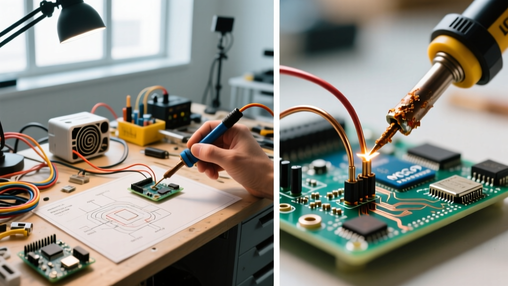
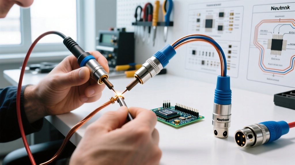
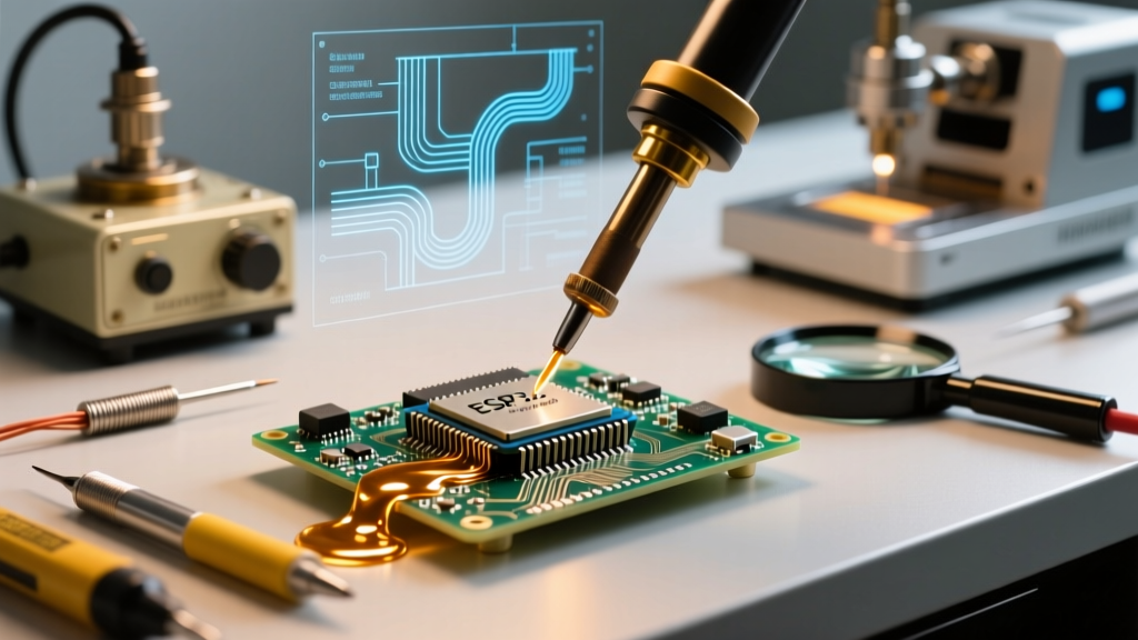
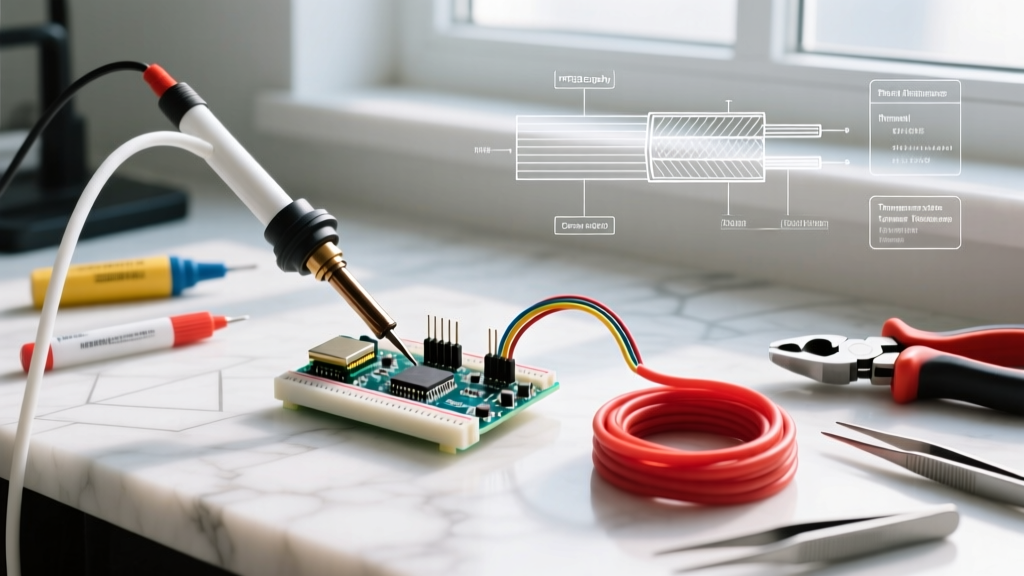
In the realm of electrical fabrication, the term soldering cable encompasses both the flexible heater cords powering your station and the high-strand-count wires you are actively joining. For this guide, we focus on the latter: selecting and preparing the wire harnesses, power cables, and signal lines that must survive the intense thermal shock of a 350°C (662°F) soldering iron tip. Using standard PVC-insulated wire in high-reliability or high-amperage applications is a critical safety failure waiting to happen.
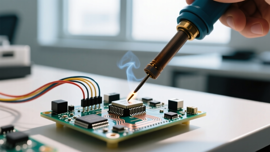
When a 350°C iron touches a standard 105°C PVC cable, the insulation doesn't just melt; it vaporizes and recedes. This phenomenon, known as burn-back, exposes bare copper far beyond the intended solder joint. In a 2026 landscape where DIY battery packs and high-wattage server power supplies routinely push 100+ amps, exposed strands can easily arc against adjacent chassis grounds, resulting in catastrophic thermal runaway.
Material Showdown: PVC vs. Silicone vs. PTFE
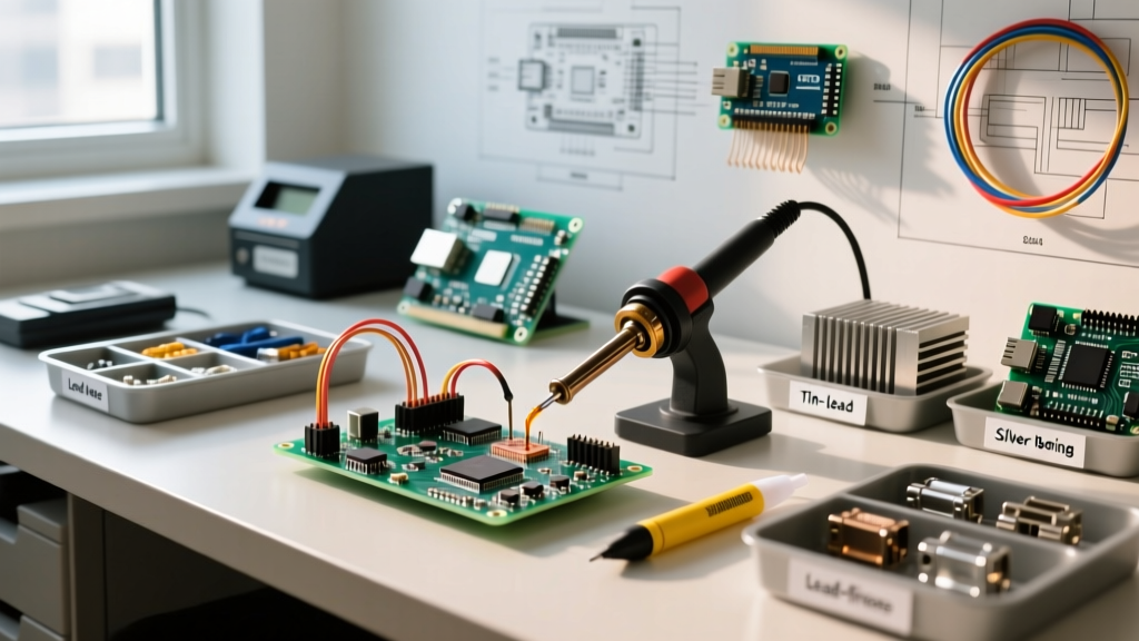
To engineer a safe soldering cable assembly, you must match the insulation polymer to the thermal and mechanical demands of the environment. Below is a comparative matrix of the three most common dielectric materials used in modern electronics fabrication.
| Material | Max Continuous Temp | Burn-Back Resistance | Flexibility | 2026 Avg Cost (per ft) | Primary Hazard |
|---|---|---|---|---|---|
| PVC (Polyvinyl Chloride) | 105°C | Poor (Recedes 5-10mm) | Stiff | $0.12 - $0.18 | Toxic HCl gas, severe burn-back |
| Silicone Rubber | 200°C | Excellent (Zero melt) | Ultra-High | $0.45 - $0.65 | Flux wicking under insulation |
| PTFE (Teflon) | 260°C | Impervious | Moderate | $1.15 - $1.40 | Cold flow, toxic fluorocarbon off-gassing >400°C |
| ETFE (Tefzel) | 150°C | Very Good | Low | $0.80 - $1.00 | Stiffness causes strand nicking during stripping |
Deep Dive: Silicone Wire Safety & Best Practices
Silicone-insulated, high-strand-count copper wire has become the undisputed standard for high-current soldering cable applications, such as RC LiPo battery harnesses, solar combiner boxes, and EV conversion busbars. A typical 12 AWG silicone cable features upwards of 680 individual 0.08mm strands, providing immense surface area for solder wetting.
The Flux Wicking Hazard
While silicone will not melt under your iron, its porous nature introduces a unique safety risk: capillary flux wicking. If you apply liquid rosin flux (like Kester 186) directly to the cable before tinning, the flux will wick centimeters up inside the insulation. Over time, trapped activated flux absorbs ambient moisture, leading to internal galvanic corrosion and eventual high-resistance failure.
- The Fix: Use a no-clean, gel-based flux such as Amtech NC-559 or Kester 245. Apply it strictly to the exposed tinned area, never allowing it to touch the silicone jacket.
- Tinning Technique: Pre-tin the cable using a high-thermal-mass iron (e.g., Hakko FX-951 with a 600°F tip) to minimize dwell time. Keep the soldering iron on the wire for no more than 3-5 seconds to prevent heat from degrading the copper stranding.
Deep Dive: PTFE Wire & The Cold Flow Danger
For avionics, military hardware, and high-frequency RF soldering cable assemblies, PTFE (Polytetrafluoroethylene) is mandatory. Governed by MIL-W-16878 specifications, PTFE utilizes silver-plated copper conductors that resist oxidation at high temperatures. However, PTFE introduces a mechanical safety hazard known as cold flow.
Cold Flow Definition: PTFE is a highly crystalline polymer that deforms continuously under mechanical pressure, even at room temperature. If you terminate a PTFE soldering cable into a standard screw terminal without a ferrule or star washer, the insulation will compress over 6-12 months, loosening the connection and creating a high-resistance arcing point.
Furthermore, if your soldering iron exceeds 400°C (752°F) and touches the PTFE jacket, it decomposes and releases highly toxic fluorocarbon gases. Always calibrate your station to a strict 320°C - 340°C ceiling when working with Teflon cables.
Tooling: Safe Stripping Without Compromising the Conductor
The most common point of failure in a soldering cable assembly occurs before the iron is even plugged in. Mechanical wire strippers often nick the outer strands of the conductor. According to NASA-STD-8739.3, any nicking or scraping of the conductor strands that reduces the cross-sectional area by more than 10% is grounds for immediate rejection of the cable.
Recommended Stripping Methodologies
- Thermal Stripping (Best for PTFE/ETFE): Tools like the Eraser Thermal Stripper use a heated blade to melt through the insulation without touching the copper. This completely eliminates strand nicking and prevents the cold-flow micro-cracks caused by mechanical blades.
- Precision Mechanical Stripping (Best for Silicone): Avoid cheap dial-strippers. Use high-precision micro-shears like the Hakko CHP-170 or automated pneumatic strippers that utilize V-blades designed specifically for ultra-flexible, high-strand-count cables.
Compliance: IPC-A-620 Clearance Standards
When designing a soldering cable harness for commercial or industrial deployment, adherence to the IPC-A-620 standard is non-negotiable. This standard dictates the acceptable insulation clearance (the gap between the end of the insulation and the start of the solder joint).
- Target Condition: The insulation should be flush with the edge of the terminal cup or pad, with a maximum clearance of 1x the wire diameter.
- Defect Condition: Insulation receding more than 2x the wire diameter, or insulation trapped inside the solder joint (which creates a hollow, high-resistance void as the plastic eventually degrades).
To maintain these tight tolerances, use a high-quality wire stop jig during the tinning phase, ensuring every cable in your batch has an identical exposed conductor length of exactly 4.5mm (for standard 2.54mm pitch connectors).
Fume Extraction and Respiratory Safety
Soldering cable assemblies often requires heavy volumes of flux, especially when wetting thick 10 AWG or 8 AWG power cables. The resulting colophony (rosin) smoke is a known respiratory sensitizer that can cause occupational asthma. The National Institute for Occupational Safety and Health (NIOSH) explicitly warns against relying on passive desk fans, which merely blow unfiltered particulate back into the operator's breathing zone.
2026 Safety Mandate: Always use a localized HEPA/Carbon fume extraction system. Units like the BOFA AD350 or the Hakko FA-400 (for lighter bench work) must be positioned within 6 inches of the solder joint to effectively capture sub-micron rosin particulates and volatile organic compounds (VOCs) before they reach the operator's face.
Final Safety Checklist for Soldering Cable Prep
- Verify Insulation Rating: Ensure the cable is rated for at least 200°C if using standard lead-free SAC305 solder (which requires 350°C+ tip temps).
- Inspect for Strand Nicking: Use a 10x loupe to inspect stripped silicone cables before tinning.
- Prevent Wicking: Apply gel flux only to the bare copper; never let liquid flux touch the jacket.
- Manage Dwell Time: If a heavy-gauge cable takes more than 5 seconds to tin, your iron lacks the thermal recovery rate. Upgrade to a 150W+ station rather than turning up the temperature dial, which will scorch the flux.