
The Metallurgy of Micro-Audio: Why Material Compatibility Matters
When it comes to soldering 3.5 mm headphone jack connectors, the margin for error is measured in millimeters and milliseconds. Unlike heavy-duty XLR or 1/4-inch TRS connectors, 3.5 mm (1/8-inch) TRS and TRRS plugs pack three or four conductive lugs into a microscopic footprint, separated by fragile insulator rings. A failure to match your solder alloy, flux chemistry, and thermal profile to the specific base metals and insulators of the jack will inevitably result in cold joints, melted sleeves, or high-impedance audio crosstalk.
This material compatibility guide breaks down the exact metallurgical and thermal requirements for successfully terminating 3.5 mm audio plugs in 2026, ensuring your DIY cables and repair jobs meet professional IPC standards.
Decoding 3.5 mm Jack Contact Materials
The first step in any successful termination is identifying the base metal and plating of your specific connector. The wetting characteristics of your solder will change drastically depending on what you are bonding to.
Nickel-Plated Brass (The Industry Standard)
Approximately 85% of consumer and pro-audio 3.5 mm jacks, such as the widely used Switchcraft 35RAPC2BH3, utilize a brass or copper-alloy base with a bright nickel plating. Nickel provides excellent corrosion resistance and mechanical hardness. However, nickel oxidizes rapidly when heated. If you attempt to solder nickel-plated lugs without an active rosin flux, the solder will ball up and refuse to wet the surface, leading to a classic 'cold joint' that will crack under the mechanical strain of plugging and unplugging the cable.
Gold-Plated Connectors (Audiophile & High-End)
Premium connectors, like the Neutrik REAN NYS367 series, feature gold plating over a nickel underlayer to guarantee optimal signal transfer and prevent galvanic corrosion.
Expert Warning: The Gold Embrittlement Myth vs. Reality.
Many DIYers fear that tin-based solders will dissolve gold and cause 'gold embrittlement' (the formation of brittle AuSn4 intermetallic compounds). While this is a critical failure mode in thick, hard-gold PCB edge connectors, the gold plating on 3.5 mm audio jacks is typically a 'flash' plating (micro-thin). The gold dissolves into the solder pool instantly upon melting, exposing the nickel underlayer, which then forms the actual structural intermetallic bond with the tin. You do not need to pre-tin and wick away the gold on standard 3.5 mm audio plugs.
Solder Alloy Compatibility Matrix
Choosing the right solder wire diameter and alloy is critical. For 3.5 mm lugs, a wire diameter of 0.020 to 0.025 inches (0.5mm - 0.6mm) is mandatory to prevent overloading the tiny cups with excess solder, which causes bridging between the Tip and Ring.
| Alloy Type | Composition | Melting Point | Compatibility with Nickel/Gold | Best Use Case |
|---|---|---|---|---|
| Leaded Eutectic | Sn63/Pb37 (Kester 44) | 183°C (361°F) | Excellent. Rapid wetting minimizes heat exposure to plastic insulators. | DIY, bespoke audiophile cables, quick repairs. |
| Lead-Free SAC | SAC305 (Sn96.5/Ag3.0/Cu0.5) | 217-220°C (422°F) | Good, but requires higher iron temps (350°C+). Increases risk of melting ABS insulators. | Commercial manufacturing, RoHS-compliant builds. |
| Silver-Bearing Leaded | Sn62/Pb36/Ag02 | 179°C (354°F) | Superior. Silver prevents silver leaching if lugs are silver-plated; excellent wetting on nickel. | High-vibration environments, stage gear repair. |
Flux Chemistry: The Hidden Audio Killer
When soldering 3.5 mm headphone jacks, flux selection is not just about making the solder stick; it is about preserving the audio signal integrity. Audio signals are low-voltage and highly susceptible to leakage currents caused by ionic residue.
- Rosin Mildly Activated (RMA): The undisputed gold standard for audio terminations. Kester 186 or similar RMA fluxes provide the necessary activators to cut through nickel oxidation but leave behind a non-conductive, hard rosin glass that traps any residual ions. This prevents high-frequency crosstalk between the tightly packed TRS/TRRS lugs.
- No-Clean Flux: While popular in modern SMT PCB assembly, no-clean fluxes can be problematic for hand-soldered 3.5 mm jacks. If not heated to the exact activation temperature profile, the residue remains slightly tacky and can attract dust and moisture, eventually creating a high-impedance leakage path between the Tip and Ring, resulting in a 'scratchy' or noisy potentiometer-like sound when the plug is rotated.
- Water-Soluble (OA) Flux: Never use this for audio jacks. It is impossible to flush the microscopic crevices inside a 3.5 mm jack barrel thoroughly enough to remove all acidic residue. It will corrode the brass lugs within months.
Thermal Limits and Insulator Melting Points
The most common catastrophic failure when soldering 3.5 mm jacks is the melting of the insulator rings that separate the conductive segments. When these melt, the lugs shift, causing internal short circuits that cannot be fixed without replacing the connector.
Material Breakdown by Insulator Type
- ABS (Acrylonitrile Butadiene Styrene): Found in 70% of budget to mid-tier jacks. Glass transition occurs around 105°C, and it begins to soften and deform at roughly 180°C. Max allowable dwell time with a 320°C iron: 2.5 seconds per lug.
- Polycarbonate (PC): Used in mid-tier connectors. Higher thermal resistance, softening around 220°C. Max allowable dwell time: 4 seconds per lug.
- PTFE (Teflon): Found in premium audiophile jacks (e.g., Furutech, high-end Switchcraft). Withstands continuous temperatures up to 260°C and melting points above 327°C. Highly forgiving; allows for longer dwell times and higher iron temperatures, making it ideal for SAC305 lead-free soldering.
Step-by-Step Material Match & Execution Flow
To achieve a structurally sound and electrically pristine termination, follow this optimized workflow tailored for 3.5 mm TRS/TRRS jacks:
1. Mechanical Preparation
Strip your audio cable to expose the conductors. For 3.5 mm jacks, 24 AWG to 28 AWG stranded copper is the physical limit. Attempting to force 22 AWG wire into the micro-cups will cause mechanical stress that cracks the solder joint over time. Tin the stripped wires with a minimal amount of Sn63/Pb37 solder.
2. Thermal Transfer Setup
Set your soldering station (e.g., Hakko FX-951 or Weller WE1010) to 320°C (608°F) for leaded solder, or 360°C (680°F) for SAC305 lead-free. Use a micro-pencil tip (e.g., Hakko T18-B2 or Weller RT1) to ensure precise thermal transfer without touching adjacent lugs or the plastic insulators.
3. The 'Three-Second' Soldering Rule
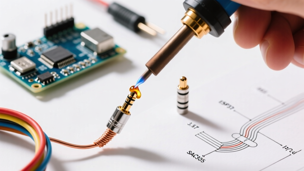
Apply a microscopic drop of fresh solder to the iron tip to create a thermal bridge. Touch the tip simultaneously to the jack lug and the pre-tinned wire. Apply a tiny amount of RMA flux-core solder wire to the joint. The entire process from iron contact to iron removal must not exceed 3 seconds. If the solder does not flow within 3 seconds, remove the iron, let the jack cool for 30 seconds, apply external liquid RMA flux, and try again. Never hold the iron to the lug while waiting for it to heat up.
4. Visual Inspection
According to the IPC J-STD-001 standard for soldered electrical assemblies, a proper through-hole or cup termination should exhibit a smooth, concave fillet with a shiny finish (for leaded alloys). The wire outline must be visible through the solder, and there must be zero evidence of the insulator ring pulling away from the metal lug.
Troubleshooting Material Mismatches
Even with careful preparation, material incompatibilities can manifest in specific failure modes:
- Solder Balling on Nickel Lugs: Your flux is depleted, or the nickel is heavily oxidized. Clean the lug with a fiberglass scratch pen, apply fresh liquid RMA flux, and re-tin.
- Dull, Grainy Joints on Gold Plugs: You have likely overheated the joint, causing excessive gold dissolution and disrupting the crystalline structure of the solder as it cooled. Desolder using a copper wick, clean with isopropyl alcohol, and re-solder with a lower temperature profile.
- Intermittent Audio / Crosstalk: Flux residue has bridged the gap between the Tip and Ring1. Submerge the termination in 99% Isopropyl Alcohol and agitate with a soft-bristle brush to dissolve and dislodge the trapped RMA rosin.
By respecting the metallurgical boundaries of nickel and gold platings, matching your solder alloy to the thermal limits of ABS and PTFE insulators, and strictly controlling your dwell time, you can fabricate 3.5 mm audio cables that rival or exceed factory-molded assemblies in both durability and signal fidelity.