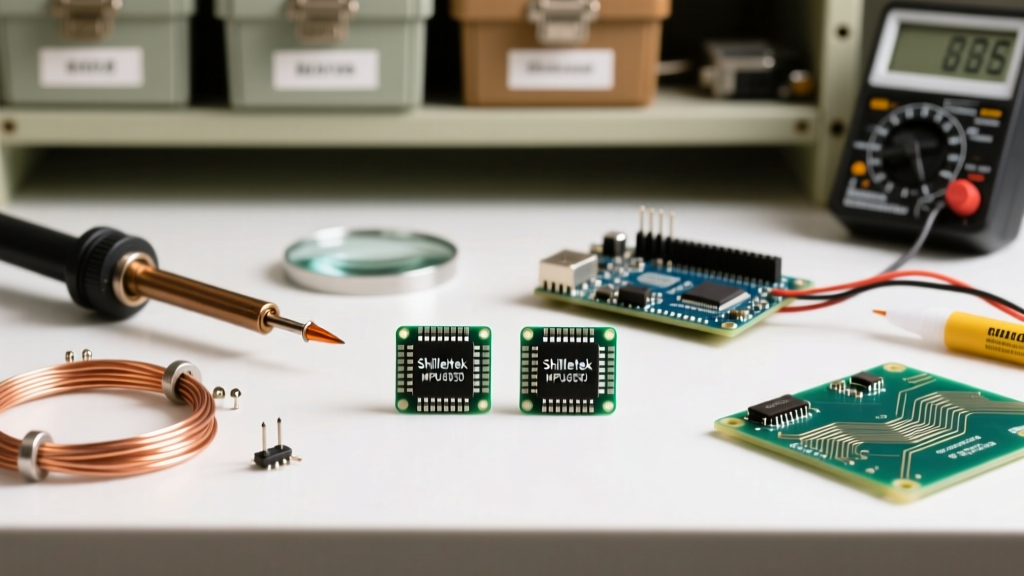

The Appeal of the Shillehtek MPU6050 Pre-Soldered 2-Pack
When building custom flight controllers, balancing robots, or motion-tracking wearables, the MPU6050 remains a staple 6-axis IMU (Inertial Measurement Unit). The Shillehtek MPU6050 pre-soldered IMU accelerometer sensor 2-pack for Arduino offers a highly cost-effective entry point for makers. By shipping with pre-attached 1x8 male pin headers, these breakout boards eliminate the need for surface-mount reflow soldering of the tiny QFN-24 chip. However, 'pre-soldered' does not always mean 'ready for every application.' Depending on your project's vibration profile, weight constraints, and spatial requirements, you must choose the correct physical integration method.
In this guide, we compare three distinct integration methods for the Shillehtek MPU6050 module, ranging from zero-solder prototyping to advanced desoldering for direct-wire integration. We will also cover critical I2C bus considerations to ensure your Digital Motion Processor (DMP) operates without packet loss.
Understanding the Shillehtek Breakout Anatomy
Before applying a soldering iron, it is vital to understand what the Shillehtek board actually does to condition the raw MPU6050 signals. According to the TDK InvenSense MPU-6050 Product Specifications, the raw chip requires a strict 3.0V to 3.46V operating voltage and relies on external pull-up resistors for I2C communication.
- Voltage Regulation: The Shillehtek board includes an onboard LDO (Low Dropout) regulator, allowing you to safely power the
VCCpin with 5V from an Arduino Uno or Nano. - I2C Pull-Ups: The breakout features 4.7kΩ surface-mount pull-up resistors on the SDA and SCL lines, meaning you do not need to enable internal Arduino pull-ups via
Wire.h. - Logic Level Translation: While the LDO handles power, the I2C data lines are still pulled up to the VCC rail. If you are using a 3.3V microcontroller (like an ESP32 or Arduino Due), you should power the Shillehtek VCC with 3.3V to prevent 5V logic from frying your MCU's GPIO pins.
Method Comparison: 3 Ways to Integrate the IMU
How you physically mount the Shillehtek module drastically affects sensor noise, particularly high-frequency mechanical resonance that can confuse the accelerometer's Z-axis.
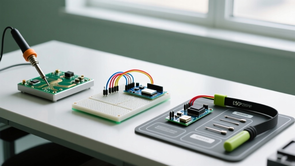
Method 1: Breadboard Prototyping (Zero-Solder)
The most common use for the pre-soldered headers is plugging the module directly into a standard solderless breadboard using Dupont jumper wires.
- Pros: Instant deployment; no thermal risk to the board; easy to swap between multiple microcontrollers.
- Cons: High susceptibility to vibration. Breadboard contacts have micro-ohms of variable resistance, which can introduce noise on the I2C lines if wires are bumped.
- Best For: Desktop coding, verifying the DMP library, and initial PID tuning for balancing robots.
Method 2: Direct-Wire Soldering (Weight-Critical Builds)
For FPV drones, micro-rovers, or RC gimbals, the pre-soldered male headers add unnecessary weight (approx. 0.8 grams) and create a lever-arm effect that amplifies vibration. Method 2 involves desoldering the headers and soldering 28AWG stranded silicone wires directly to the castellated pads.
- Pros: Maximum weight reduction; lowest profile; superior vibration dampening when mounted with double-sided foam tape.
- Cons: High risk of lifting copper pads if desoldering is done improperly; permanent connection.
- Best For: Aerospace, competitive mini-drones, and wearable motion capture suits.
Method 3: Perfboard with Female Headers (Modular Permanent)
This hybrid method involves soldering 1x8 female headers to a custom perfboard or PCB, allowing the Shillehtek module to plug in securely while maintaining a rigid, permanent electrical connection.
- Pros: Rigid connection eliminates breadboard bounce; allows for easy IMU replacement if the gyro is damaged in a crash.
- Cons: Adds the combined weight of male and female headers; increases Z-axis height.
- Best For: Modular robotics platforms and educational kits where hardware swapping is common.
Advanced Soldering: Safely Removing Pre-Soldered Headers
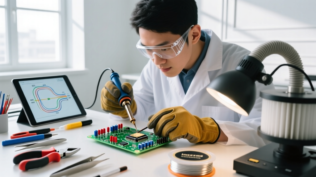
If you choose Method 2, you must remove the factory headers without destroying the FR4 substrate. The Shillehtek boards use lead-free or high-temperature rosin-core solder, which requires specific thermal management.
Pro-Tip: Never attempt to pry the plastic header block off while the solder is semi-molten. The mechanical stress will rip the copper annular rings right off the fiberglass board, instantly ruining the breakout.
Step-by-Step Desoldering Protocol
- Apply Flux: Coat the header pins generously with a high-quality tacky flux (e.g., Amtech NC-559 or ChipQuik). Flux lowers the surface tension and accelerates heat transfer.
- Add Lead Solder: Using your soldering iron set to 360°C with a chisel tip, apply a small amount of 63/37 leaded solder to each pin. This alloys with the factory lead-free solder, drastically lowering its melting point.
- Use Desoldering Braid: Press a 2.5mm copper desoldering wick (pre-fluxed) over the pins. Apply the iron directly on top of the braid. Hold for 3-4 seconds until the solder wicks up into the copper mesh.
- Extract: Once all pins are free of bulk solder, gently push the plastic header block out from the bottom using a pair of flat-nosed tweezers. If it resists, apply more heat; do not force it.
- Clean the Pads: Wipe the pads with isopropyl alcohol (99%) to remove flux residue before tinning them for your direct wires.
I2C Wiring and Pull-Up Resistor Considerations
The MPU6050 communicates via I2C. When wiring multiple Shillehtek modules to a single Arduino, you must manage the I2C addresses and bus capacitance.
By default, the AD0 pin is pulled low via an onboard resistor, giving the module the I2C address 0x68. If you need a second IMU on the same bus (taking advantage of the 2-pack), you must bridge the AD0 pad to VCC to change the address to 0x69. This requires delicate soldering with 0.1mm enameled copper wire.
Furthermore, the Arduino Wire Library defaults to a 100kHz I2C clock speed. The MPU6050's Digital Motion Processor (DMP) generates a high volume of FIFO data. To prevent I2C buffer overflows and read errors, you should increase the bus speed to 400kHz in your setup() loop:
Wire.begin();
Wire.setClock(400000); // Set I2C to Fast Mode
Integration Method Comparison Chart
| Integration Method | Vibration Resistance | Added Weight | Soldering Skill Required | Ideal Application |
|---|---|---|---|---|
| Breadboard (Dupont) | Very Low | ~3.5g (wires) | None | Desktop prototyping, code testing |
| Direct-Wire (Desoldered) | Excellent | ~0.2g (wires) | Advanced (Desoldering) | FPV drones, gimbals, wearables |
| Perfboard (Female Headers) | High | ~1.5g (headers) | Intermediate | Modular rovers, robotics kits |
Troubleshooting Common MPU6050 I2C Errors
When integrating the Shillehtek 2-pack, makers frequently encounter I2C lockups. Here is how to diagnose them based on your physical soldering method:
- 'I2C Zeroes' or Hanging Code: This usually indicates missing pull-up resistors or a loose ground connection. If using long Dupont wires (over 15cm), the capacitance of the wire can degrade the I2C signal edges. Keep SDA/SCL wires under 10cm, or add external 2.2kΩ pull-ups to the 3.3V rail.
- Erratic Yaw/Pitch/Roll Data: If your physical mount is loose (Method 1), the gyro will read the micro-vibrations of the breadboard springs. Switch to Method 2 and mount the IMU using 1mm double-sided VHB foam tape to act as a mechanical low-pass filter.
- Address Not Found (I2C Scanner): Verify that the VCC pin is receiving at least 3.3V. The onboard LDO requires a minimum voltage differential to regulate the core MPU6050 chip. If powering from a 3.3V Arduino pin, ensure the voltage isn't sagging under load.
Final Verdict: Maximizing the 2-Pack Value
The Shillehtek MPU6050 pre-soldered IMU 2-pack is an exceptional value for Arduino enthusiasts, provided you treat the pre-soldered headers as a convenience rather than a strict limitation. For stationary projects like robotic arms or weather stations, the plug-and-play breadboard method is perfectly adequate. However, for dynamic, high-vibration environments, taking the time to properly desolder the headers and direct-wire the module using the techniques outlined above will yield vastly superior sensor data, reducing the computational load on your PID control loops. For more insights on handling 6-axis sensors, the Adafruit MPU-6050 Guide offers excellent supplementary wiring diagrams and library recommendations.