
The Thermal Danger Zone: Why LEDs Fail During Soldering
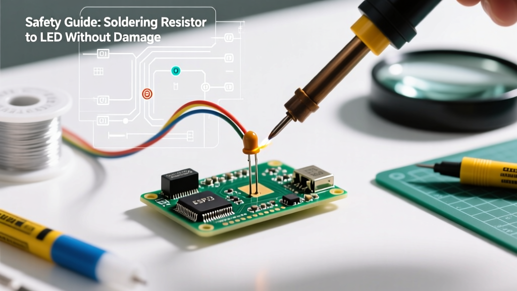
When soldering resistor to LED assemblies, the primary adversary is thermal runaway. Standard 5mm through-hole LEDs, such as the ubiquitous Lite-On LTL-307EE, feature an epoxy resin body that begins to soften, cloud, and degrade at temperatures exceeding 125°C. More critically, the internal gold wire bond connecting the semiconductor die to the anode post can detach if subjected to rapid thermal expansion or prolonged heat exposure. This results in a catastrophic open-circuit failure, often referred to by engineers as 'popcorning' the LED.
Conversely, standard 1/4W carbon film or metal film resistors (like the Yageo CFR series) are far more robust, typically rated to withstand ambient temperatures up to 155°C and brief soldering spikes up to 260°C. The safety challenge, therefore, lies in delivering enough heat to form a reliable metallurgical joint without exceeding the thermal limits of the more fragile LED component.
Pro-Tip: Never use a high-wattage, unregulated soldering gun (e.g., 100W+ transformer guns) for LED work. The massive thermal mass and uncontrolled tip temperatures will instantly melt the LED lens and destroy the internal die.
Essential Safety Gear & Setup for 2026
Safety in electronics assembly encompasses both component protection and user health. Rosin-based flux fumes contain colophony, a known respiratory sensitizer that can cause occupational asthma if inhaled repeatedly. Proper setup is non-negotiable.
Fume Extraction & PPE
- Fume Extractor: A dedicated HEPA and activated carbon filter unit is mandatory. The Hakko FA-400 (approx. $65) remains a benchtop staple, but for heavy production, enclosed bench hoods with external venting are recommended by industrial hygiene standards.
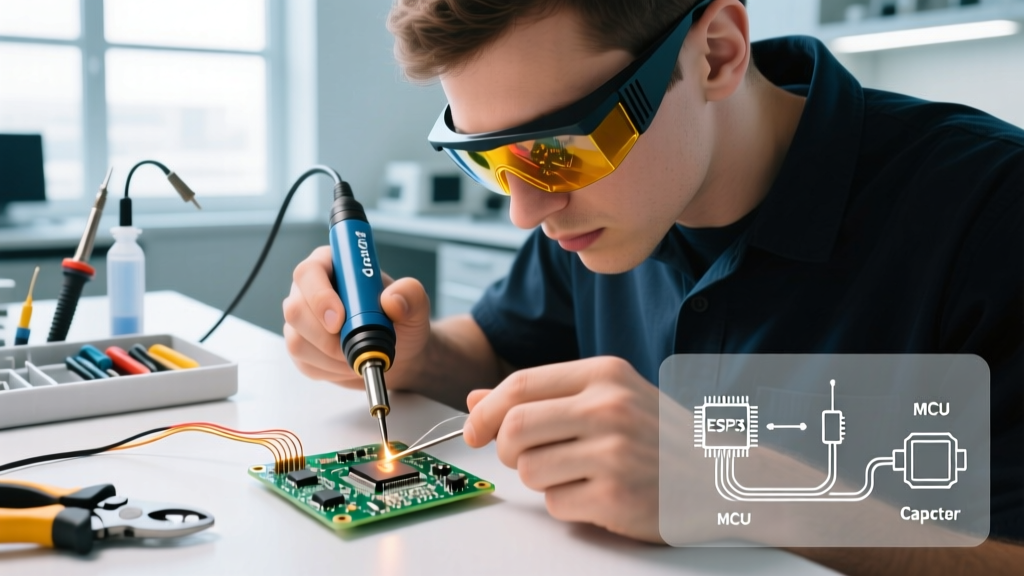
- Eye Protection: ANSI Z87.1 rated safety glasses protect against microscopic solder splatter and clipped wire leads, which can launch at high velocities.
- ESD Mat: While standard LEDs are not highly sensitive to Electrostatic Discharge (ESD), working on a grounded silicone mat prevents accidental shorts if you later transition to static-sensitive components like MOSFETs or microcontrollers.
Temperature-Controlled Irons & Solder Alloy Selection
In 2026, lead-free solders like SAC305 (Sn96.5/Ag3.0/Cu0.5) are the commercial standard, melting at roughly 217°C. However, for DIY and prototyping where soldering resistor to LED joints is common, 63/37 SnPb (Tin/Lead) eutectic solder remains the superior choice for thermal safety. Eutectic solder melts at a much lower 183°C and transitions instantly from liquid to solid without a plastic (pasty) phase, drastically reducing the time the LED is exposed to heat.
Use a temperature-controlled station. The Pinecil V2 (~$28) offers rapid thermal recovery and precise digital control, while the Weller WE1010NA (~$125) provides heavy-duty thermal mass for continuous bench work. Set your iron to 320°C (608°F) when using 63/37 solder with a Kester 44 rosin core.
Step-by-Step: Safe Soldering Technique
Follow this precise sequence to ensure a strong mechanical and electrical bond while protecting the LED.
- Pre-Tin the Leads: Apply a tiny amount of solder to the exposed resistor lead and the LED anode/cathode individually before joining them. This reduces the time the iron needs to dwell on the final joint.
- Form a Mechanical Joint: Do not simply hold the two wires together and apply solder. Strip the resistor lead, wrap it tightly around the LED lead using a modified Western Union splice, and crimp it flat with needle-nose pliers. A solder joint must never bear mechanical stress.
- Apply a Heat Sink: Clamp a small hemostat or copper alligator clip onto the LED lead, positioned between the solder joint and the LED epoxy body. This metal mass will absorb and dissipate excess heat traveling up the wire, protecting the internal die.
- The 3-Second Rule: Touch the iron tip to the mechanical joint, then immediately feed the rosin-core solder into the joint (not directly onto the iron tip). The flux will activate, and the solder will wick into the splice. Remove the solder, then remove the iron. The entire process should take no more than 2 to 3 seconds.
- Cool Naturally: Do not blow on the joint or quench it in water. Forced cooling can cause micro-fractures in the solder crystalline structure and thermal shock to the LED lens.
Component Thermal Tolerances & Parameters
Understanding the exact limits of your materials is critical for process control. Refer to this matrix when planning your assembly.
| Component / Material | Max Continuous Temp | Max Soldering Temp (5s) | Recommended Solder Alloy |
|---|---|---|---|
| Standard 5mm THT LED (Epoxy) | 85°C | 260°C (at 2mm from body) | 63/37 SnPb Eutectic |
| 1/4W Metal Film Resistor | 155°C | 350°C | 63/37 SnPb or SAC305 |
| Kester 44 Rosin Flux | N/A | Activates at ~150°C | Use with SnPb |
| Adhesive-Lined Heat Shrink | 125°C | Shrinks at 120°C | N/A (Apply post-solder) |
Insulation and Electrical Short Prevention
A bare solder joint connecting a resistor to an LED is a short circuit waiting to happen, especially if the assembly is housed in a metal chassis or subjected to vibration. Electrical tape is a poor long-term solution; its adhesive degrades, leaving a gummy residue and exposing the joint.
Instead, use dual-wall adhesive-lined heat shrink tubing. Products like the 3M EPS200 series feature an inner layer of hot-melt adhesive that flows when heated, creating a waterproof, strain-relieved seal around the joint. Slide a piece of 3/32" or 1/8" tubing over the resistor lead before soldering. Once the joint has cooled to room temperature, slide the tubing over the splice and apply heat using a dedicated hot air gun or a lighter held at a safe distance. Avoid using the soldering iron barrel to shrink the tubing, as this can transfer excess heat back into the LED.
Troubleshooting Common Failure Modes
Even with strict safety protocols, errors occur. Here is how to diagnose and fix the most common issues when soldering resistor to LED circuits.
1. The 'Cold' or 'Disturbed' Joint
Symptom: The solder joint looks dull, grainy, or bulbous, and the connection is intermittent. Cause: The joint was moved before the solder fully solidified, or the iron temperature was too low to properly wet the copper leads. Fix: Apply a small amount of fresh liquid flux (e.g., Chip Quik SMD291AX) and reflow the joint with a clean, tinned iron tip at 330°C. Hold the wires perfectly still until the solder loses its liquid shine.
2. Melted or Clouded LED Lens
Symptom: The clear or colored epoxy dome of the LED is flattened, scorched, or opaque. Cause: Excessive dwell time (iron applied for >5 seconds) or soldering too close to the LED base (less than 2mm clearance). Fix: The LED is permanently damaged and must be desoldered and replaced. The internal phosphor or die structure is compromised, leading to severe color shifting and reduced lumen output.
3. Solder Wicking Up the Lead
Symptom: Solder travels up the LED lead toward the epoxy body, creating a rigid, brittle wire that can snap under vibration. Cause: Over-application of solder or using a highly active flux with excessive heat. Fix: Use solder wick (desoldering braid) to remove excess solder. Ensure you are using only enough solder to form a smooth fillet at the base of the mechanical splice.
Further Reading & Authoritative Resources
To deepen your understanding of through-hole soldering metallurgy and bench safety, consult these industry-standard resources:
- SparkFun: How to Solder (Through-Hole) - An exhaustive visual guide covering joint geometry, flux chemistry, and tool maintenance.
- Adafruit Guide to Excellent Soldering - Detailed breakdowns of iron tip selection, thermal mass management, and ESD safety protocols.
Frequently Asked Questions
Can I use a butane-powered cordless soldering iron for LED work?
While cordless irons like the Master Appliance UltraTorch are excellent for field repairs on thick gauge wires, they lack the precise thermal regulation required for delicate components. The tip temperature can fluctuate wildly, making it very easy to overheat and destroy an LED. Stick to digitally regulated, plug-in stations for component-level work.
Does the resistor need to be on the anode or cathode side of the LED?
From an electrical standpoint, a series current-limiting resistor functions identically on either the anode (positive) or cathode (negative) side. However, from a safety and troubleshooting perspective, placing the resistor on the anode side is considered best practice. If a short circuit occurs downstream of the LED, the resistor will still limit the current, potentially saving the LED from catastrophic overcurrent failure.
How do I clean the flux residue after soldering?
Rosin flux residue (like that from Kester 44) is technically non-corrosive and non-conductive, but it can trap moisture and dust over time, leading to parasitic leakage currents. Clean the joint using a stiff-bristled ESD-safe brush and 99% Isopropyl Alcohol (IPA). Do not use 70% IPA, as the 30% water content can cause oxidation on the freshly cleaned joint.