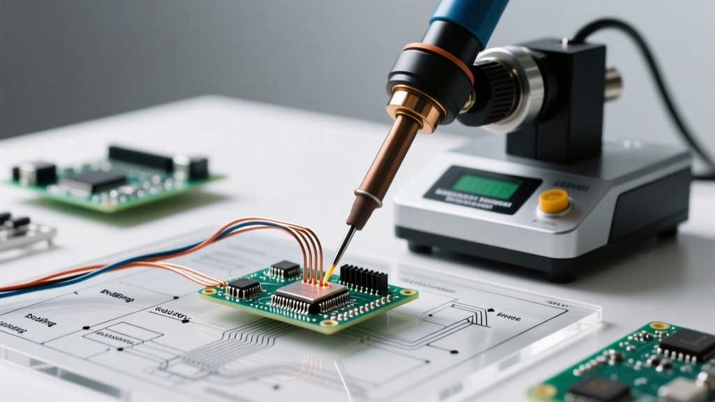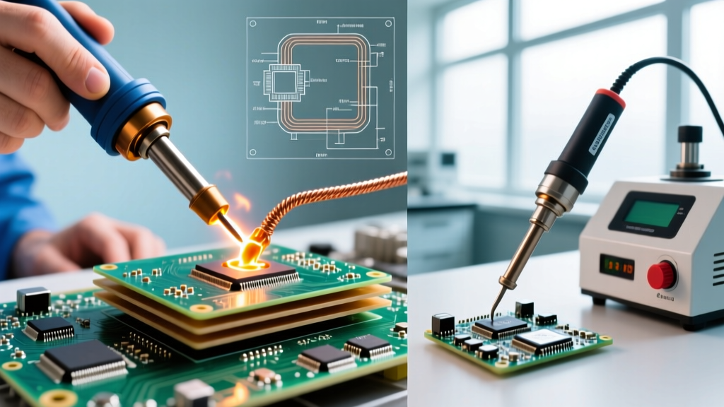

The High-Stakes Reality of Industrial Desoldering
In consumer electronics repair, a slipped iron might ruin a $50 motherboard. In aerospace, automotive, and medical device manufacturing, the failure to properly remove soldering joints from high-density, multi-layer printed circuit boards (PCBs) can compromise mission-critical systems and result in catastrophic field failures. As we navigate the component landscape of 2026, the proliferation of 12-to-24-layer HDI (High-Density Interconnect) boards, massive copper ground planes, and complex BGA (Ball Grid Array) footprints has fundamentally changed the thermal dynamics of rework.
When engineers need to remove soldering connections from modern assemblies, they are battling extreme thermal mass and strict lead-free alloy requirements. The dominant SAC305 (Sn96.5/Ag3.0/Cu0.5) alloy melts at approximately 217°C to 220°C, but achieving proper liquidus and capillary flow on a 16-layer board with heavy thermal vias requires localized tip temperatures exceeding 360°C. This article explores the professional-grade methodologies, tooling, and physics required to safely extract components and clean pads in high-reliability industry applications.
The Physics of Rework: Thermal Mass vs. Delta-T
The most common mistake technicians make when attempting to remove soldering material is cranking up the temperature on a standard soldering iron to compensate for a board's thermal mass. This approach violates the fundamental physics of heat transfer and guarantees localized damage.
Understanding Z-Axis Expansion and CTE Mismatch
PCBs are constructed from alternating layers of copper and dielectric materials like FR-4 or polyimide. These materials have vastly different Coefficients of Thermal Expansion (CTE). When a high-wattage iron applies intense, localized top-side heat without bottom-side pre-heating, the z-axis (thickness) of the board expands rapidly. This CTE mismatch generates immense mechanical stress on the plated through-holes (PTHs), leading to micro-cracks in the via barrels—a latent defect that will eventually cause an open circuit in the field.
Expert Warning: Never exceed a thermal ramp rate of 3°C to 4°C per second when heating multi-layer ceramic capacitors (MLCCs) or large BGA packages. Rapid thermal shock will cause micro-fractures in the ceramic dielectric, leading to short circuits under voltage bias.Core Technologies to Remove Soldering in High-Reliability Sectors
Industrial rework labs rely on a triad of specialized equipment to manage heat distribution and material extraction. Selecting the right tool depends entirely on the component package, the board's layer count, and the specific alloy in use.
1. Pneumatic Desoldering Guns (Through-Hole & Heavy Lugs)
For removing through-hole components, heavy transformer lugs, or connectors with large ground pins, pneumatic desoldering guns are the undisputed industry standard. Tools like the Hakko FR-301 (priced around $225) or the handpieces paired with the Pace MBT 350 station (upwards of $1,300) utilize a built-in vacuum pump and a hollow, Teflon-coated heating nozzle.
- Mechanism: The hollow tip surrounds the component lead, melting the solder in the barrel. A trigger activates the vacuum, instantly aspirating the molten alloy into a collection chamber.
- Industrial Advantage: Eliminates the need for secondary cleanup. High-end models feature ceramic heating elements that recover heat in under 2 seconds, crucial for pulling 40-pin DIP connectors without freezing on the final pins.
2. Advanced Hot Air & Infrared Rework (SMD & BGA)
Surface Mount Devices (SMDs) and BGAs cannot be removed with contact irons. Industrial labs utilize advanced hot air stations like the Quick 861DW ($250) or the JBC JTSE Intelligent Station ($1,450). In 2026, intelligent stations dominate the market because they dynamically adjust power output based on the thermal demand sensed at the cartridge tip or nozzle.
- Airflow Metrics: Precision is paramount. Technicians must balance temperature (typically 350°C - 380°C for SAC305) with airflow (measured in liters per minute). Too much airflow will blow adjacent 0402 or 0201 passives off their pads; too little will fail to transfer heat to the component's thermal pad.
- Nozzle Selection: Custom-fitted nozzles that encompass the entire QFP or BGA package are mandatory to ensure simultaneous heating of all leads, preventing pad tearing.
3. Capillary Desoldering Braids (Fine-Pitch Cleanup)
Once a component is lifted, residual solder must be removed to achieve a coplanar surface for the replacement part. Desoldering braid (wick) relies on capillary action and flux chemistry to absorb molten solder. Chemtronics Soder-Wick and Goot Wick remain the gold standards, with 10-foot spools costing between $8 and $15.
- Flux Chemistry: Braids are coated in flux to break down oxides. For aerospace and medical boards, No-Clean (NC) or Rosin Mildly Activated (RMA) braids are required. Water-soluble (WS) braids are highly corrosive and must be aggressively washed, which is often impossible under tight-pitch BGAs.
- Sizing: Use a 2.0mm to 2.5mm braid for 0805 and fine-pitch QFPs. Reserve 5.0mm+ braids for large ground planes and D-PAK thermal tabs.
Comparative Matrix: Selecting the Right Removal Method
| Methodology | Target Application | Optimal Temp (SAC305) | Est. Equipment Cost | Risk Profile |
|---|---|---|---|---|
| Pneumatic Desoldering Gun | Through-hole, heavy lugs, DIP ICs | 360°C - 390°C | $220 - $1,400 | Moderate (Pad lifting if forced) |
| Hot Air Rework Station | SMDs, QFNs, BGAs, SOT-23 | 350°C - 380°C (Air) | $250 - $1,500 | High (Thermal shock, blown parts) |
| Desoldering Braid / Wick | Pad cleanup, fine-pitch prep | 340°C - 360°C (Iron) | $10 - $20 (Consumable) | Low (Requires proper flux matching) |
| Bottom-Side Pre-Heater | Multi-layer HDI boards, Ceramic | 100°C - 130°C (Ambient) | $400 - $900 | None (Mitigates all other risks) |
Step-by-Step Protocol: Removing Soldering from a 12-Layer Aerospace PCB
When tasked with replacing a faulty microcontroller on a 12-layer board with internal ground planes, follow this strict thermal protocol to ensure compliance with high-reliability standards.
- Flux Application: Apply a high-tack, RMA-based tacky flux (e.g., Amtech NC-559-V2) to all pins of the target IC. Do not skip this step; fresh flux lowers the surface tension of the old, oxidized OEM solder, drastically reducing the required dwell time.
- Pre-Heat Phase: Place the PCB on an infrared pre-heater (such as the Pace PH-100). Ramp the bottom-side temperature to 110°C over 3 minutes. This reduces the Delta-T (temperature difference) required from your top-side tool, protecting internal vias.
- Component Extraction: Using a JBC hot air station with a custom quad nozzle, apply 360°C air at 40% flow. Sweep evenly across the package. Once the solder reaches liquidus (indicated by a slight 'shimmer' and the component floating on surface tension), lift the IC vertically with precision vacuum tweezers. Never drag or pry the component.
- Pad Planarization: Switch to a low-thermal-mass soldering iron (e.g., JBC C245 cartridge) set to 350°C. Lay a 3.0mm Chemtronics No-Clean braid flat over the pads. Press the iron down gently and drag at a rate of 2mm per second. The capillary action will wick away the remaining solder, leaving perfectly flat, oxidized-free pads.
- Inspection & Cleaning: Inspect the pads under a 40x stereo microscope. If any solder bridges remain, repeat the braid process with fresh flux. Clean the area with 99% IPA and a lint-free swab if required by your specific IPC class guidelines.
Critical Failure Modes and Edge Cases
Even with premium equipment, operators must be vigilant against specific failure modes inherent to the desoldering process:
- Pad Lifting (Measling): Occurs when a technician attempts to remove a component before the solder has fully reached liquidus across the entire joint. The mechanical force tears the copper pad away from the underlying FR-4 substrate. Once a pad is lifted, the board requires complex epoxy bonding and jumper wire routing to meet IPC standards for rework and modification.
- Tombstoning and Drawbridging: When using hot air to remove a cluster of small passives, uneven heating can cause one side of a capacitor's solder to melt before the other. Surface tension will pull the component upright (tombstoning) or cause adjacent solder balls to merge (drawbridging).
- Flux Carbonization: Leaving an iron on a desoldering braid for more than 4-5 seconds will burn the flux, leaving a hard, black carbon residue that acts as an insulator. This residue is nearly impossible to remove and will prevent the new component from wetting to the pad.
'In high-reliability environments, the goal of rework is not just to replace the component, but to ensure the thermal and mechanical integrity of the surrounding assembly remains uncompromised. Proper heat management and flux chemistry are the true metrics of a successful rework operation.' — Guidelines adapted from the NASA Electronic Parts and Packaging (NEPP) Program workmanship standards.
Industry Standards and Compliance
Industrial rework is not a matter of guesswork; it is governed by stringent international standards. Facilities performing defense, medical, or aerospace rework must certify their technicians and processes against IPC-7711/21 (Rework, Modification, and Repair of Electronic Assemblies). This standard dictates the exact allowable thermal profiles, the acceptable methods for pad replacement, and the cleaning requirements post-desoldering.
Furthermore, as the industry continues to adopt low-temperature and specialized alloys (such as SnBiAg for heat-sensitive RF modules) alongside traditional SAC305, understanding the exact metallurgical composition of the OEM solder is mandatory before any heat is applied. Using a standard 380°C profile on a Bismuth-based alloy will instantly vaporize the flux and severely damage the component packaging.
Frequently Asked Questions (FAQ)
Can I use a standard 60W iron to remove soldering from a ground plane?
No. A standard 60W iron lacks the thermal recovery rate to overcome the heat dissipation of a large copper ground plane. The tip temperature will plummet upon contact, leading to cold joints and pad damage. Use a high-wattage station (100W+) with a heavy, chisel-style thermal mass tip, paired with a bottom-side pre-heater.
Why does my desoldering braid keep sticking to the PCB pads?
This occurs when the flux has burned off or the iron temperature is too low, causing the molten solder to freeze and fuse the copper braid to the copper pad. Always ensure your iron is at least 340°C, use fresh braid, and never pull the braid upward; always drag it laterally across the pads.
Is it necessary to clean no-clean flux after desoldering?
While 'no-clean' fluxes are designed to remain on the board, the high heat of desoldering can alter their chemical structure, potentially making them conductive or corrosive over time in humid environments. In Class 3 aerospace applications, cleaning with saponifiers or high-purity IPA is strongly recommended post-rework.