
The Hidden Vulnerabilities of Potentiometer Soldering
Potentiometers (pots) are ubiquitous in audio mixing consoles, motor control circuits, and precision instrumentation. Yet, they are uniquely vulnerable during the assembly and repair process. Unlike standard resistors or ceramic capacitors, a potentiometer contains a delicate mechanical wiper that rides on a resistive track made of carbon, cermet, or conductive plastic. Furthermore, the housing is often constructed from heat-sensitive phenolic resins or thermoplastics. Poor potentiometer soldering techniques routinely lead to warped casings, degraded resistive tracks, and flux intrusion, resulting in scratchy audio, dead spots, or total component failure.
From a safety perspective, the risks extend beyond component damage. Soldering near open potentiometer casings exposes the technician to concentrated flux fumes and presents electrostatic discharge (ESD) risks to the active circuitry connected to the wiper. This guide details the exact thermal thresholds, chemical hazards, and mechanical protocols required for safe and reliable potentiometer soldering in 2026.
The Thermal Danger Zone: Exact Temperature Limits
The most common failure mode in potentiometer soldering is thermal degradation. Technicians often default to high-temperature settings (380°C+) to achieve fast wetting, but this is catastrophic for pot internals. The resistive element and the wiper's physical tension are calibrated at room temperature; excessive heat transfers through the copper lugs into the casing, softening the internal plastics and altering the wiper's contact pressure.
| Potentiometer Type | Popular Model | Max Tip Temp | Max Dwell Time | Flux Sensitivity |
|---|---|---|---|---|
| Carbon Composition | Alps RK09 (Audio) | 300°C (572°F) | 3 Seconds | High |
| Cermet Trimmer | Bourns 3296W | 350°C (662°F) | 5 Seconds | Moderate |
| Conductive Plastic | Vishay Spectrol 534 | 280°C (536°F) | 2 Seconds | Extreme |
| Wirewound | Bourns 3590S | 360°C (680°F) | 5 Seconds | Low |
As outlined in the NASA Workmanship Training Standards for heat-sensitive components, thermal shunting (using a heat sink clip) is mandatory when soldering to lugs that are mechanically coupled to sensitive internal structures. Always use a chisel tip (e.g., Hakko T18-D12 or JBC C245-764) to maximize surface area contact, allowing you to lower the station temperature while maintaining rapid heat transfer.
Flux Intrusion and Chemical Safety Hazards
Flux intrusion is a silent killer of potentiometer functionality. When rosin-activated (RA) or water-soluble flux boils, it liquefies and releases volatile organic compounds (VOCs). If the soldering iron is applied too close to the casing seam, capillary action can draw boiling flux directly into the potentiometer housing. Once cooled, this residue coats the resistive track, causing severe contact resistance spikes and 'scratchy' noise when the shaft is rotated.
Expert Rule of Thumb: Never apply solder or flux directly to the potentiometer lug. Pre-tin the wire, and use only the minimal flux required to wet the joint. Keep the iron tip at least 3mm away from the plastic casing seam.
From an occupational health standpoint, boiling flux generates colophony fumes, a known respiratory sensitizer. The CDC National Institute for Occupational Safety and Health (NIOSH) emphasizes that localized exhaust ventilation is critical when soldering. Because potentiometers often require the technician to lean in closely to inspect the small lugs, a high-quality benchtop fume extractor is non-negotiable. In 2026, HEPA-filtered extractors like the Metcal BTX-208 or the Hakko FA-400 (priced around $85 to $650 respectively) are industry standards for capturing sub-micron particulates before they reach the breathing zone.
Step-by-Step Safe Soldering Protocol
To prevent thermal, chemical, and mechanical damage, follow this strict operational sequence when terminating wires to panel-mount or PCB potentiometers:
- Mechanical Preparation: Strip the wire to exactly 3mm (1/8 inch). Twist the strands tightly and pre-tin the wire using a low-solids, no-clean flux core solder (e.g., Kester 245 or Chip Quik NC191, 0.5mm diameter). Do not pre-tin the potentiometer lug.
- Thermal Shunting: Attach a small alligator clip or copper hemostat to the lug, positioned between the solder joint area and the potentiometer casing. This acts as a heat sink, absorbing thermal energy before it reaches the internal plastics.
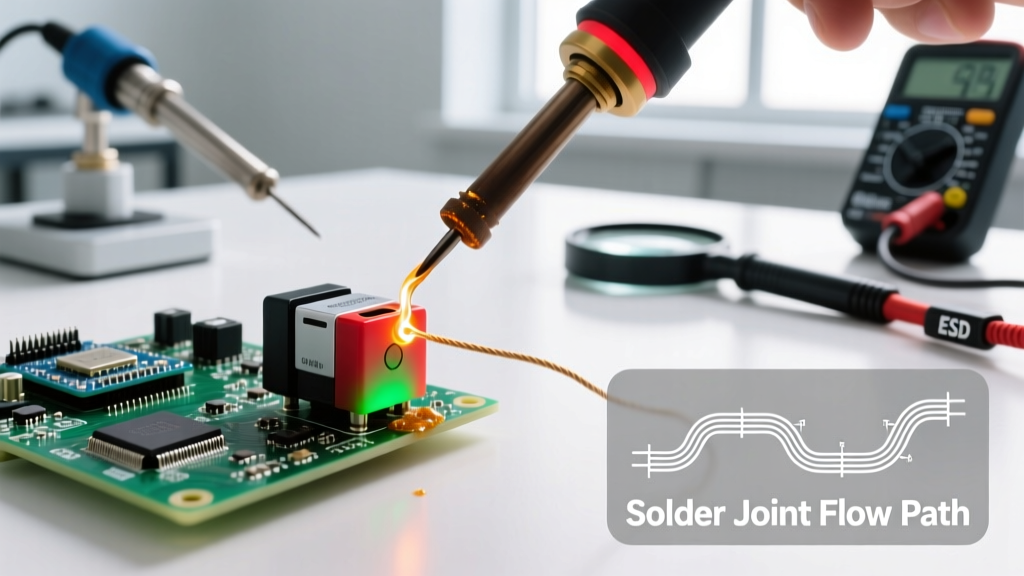
- The 3-Second Join: Set your soldering station to 320°C (608°F) for standard cermet/carbon pots. Touch the iron tip to the pre-tinned wire and the lug simultaneously. The pre-tinned wire should melt and flow onto the lug within 1.5 to 3 seconds. Remove the iron immediately.
- Static Cooling: Hold the wire completely still for 4 seconds. Blowing on the joint or moving the wire while the solder is in its plastic (semi-solid) state will cause a cold joint and mechanically stress the lug's internal rivet.
- Inspection and Cleaning: Inspect the joint with a 10x loupe. If flux residue is present near the casing, clean it gently with a lint-free swab and 99% isopropyl alcohol, ensuring no liquid is pushed into the casing seams.
Mechanical Stress and Pin Shearing Prevention
Potentiometer lugs are typically stamped brass or copper, riveted or swaged into the resistive element board. Applying downward pressure with a soldering iron, or pulling on the wire while the solder is molten, can bend the lug. This bending force is transferred directly to the resistive track, causing micro-fractures in cermet elements or delamination in carbon tracks.
Always use a 'helping hands' tool or a custom PCB jig to hold the wire in place before applying the iron. The wire should be mechanically secured so that the solder joint bears zero mechanical load. For PCB-mount trimmers like the Bourns 3296 series, ensure the component is fully seated flush against the board before soldering; otherwise, the act of pressing the iron down will torque the pins and crack the internal ceramic substrate.
ESD Safety: Protecting the Connected Circuitry
While the passive resistive track of a potentiometer itself is not sensitive to Electrostatic Discharge (ESD), the wiper terminal is usually connected directly to the high-impedance input of an operational amplifier, a microcontroller ADC, or a digital potentiometer interface. These active components are highly susceptible to ESD damage.
- Grounding: Always use a grounded ESD wrist strap (1 megohm safety resistor) connected to a common point ground.
- Matting: Work on a dissipative ESD mat (10^6 to 10^9 ohms/sq). Never solder potentiometers on bare metal benches or standard plastic surfaces, which can generate triboelectric charges exceeding 10,000V.
- Iron Tip Leakage: Verify that your soldering iron tip has less than 2mV of AC leakage to ground. Ungrounded or poorly maintained iron tips can inject stray voltages directly into the wiper, instantly destroying the gate oxide of connected MOSFETs or CMOS inputs.
Troubleshooting Post-Solder Potentiometer Failures
If a potentiometer exhibits erratic behavior after soldering, diagnose the failure mode using these indicators:
- Scratchy Audio / Dead Spots: Caused by flux intrusion or thermal warping altering wiper pressure. Fix: Sometimes salvageable by injecting specialized contact cleaner (e.g., DeoxIT F5S) into the casing and rotating the shaft 50 times, but often requires replacement.
- Open Circuit on Pin 1 or 3: Caused by mechanical lug shearing or excessive heat melting the internal swage. Fix: Component is destroyed; replace and review thermal shunting technique.
- Non-Linear Taper: Caused by localized overheating of the carbon/cermet track, altering its resistivity. Fix: Replace component and lower iron temperature by 20°C.
Mastering potentiometer soldering safety requires a shift in mindset from simple electrical connection to holistic thermal and mechanical management. By respecting the strict dwell times, utilizing thermal shunts, and maintaining rigorous ESD and fume extraction protocols, you ensure both the longevity of your sensitive components and the safety of your workspace.