
The Evolution of Soldering Magnification in 2026
As surface-mount technology (SMT) continues to shrink, with 0201 and 01005 imperial components becoming standard in modern consumer electronics and IoT devices, the naked eye is no longer sufficient for precision assembly. Choosing the right magnifier for soldering is no longer just about making small things look bigger; it is a critical decision involving depth perception, working distance, optical latency, and ergonomic sustainability. According to the IPC-A-610 standards for electronic assembly acceptability, proper visual inspection requires specific magnification levels based on the class of the product, making your choice of optics a matter of both quality assurance and physical health.
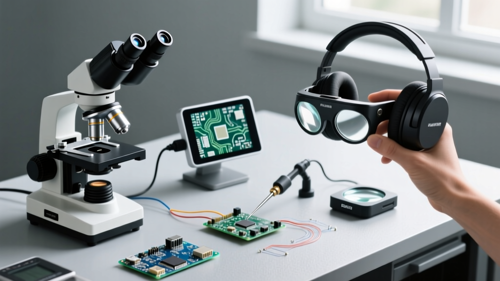
In this comprehensive method comparison, we dissect the three dominant magnification technologies available to electronics hobbyists, repair technicians, and production engineers: Optical Stereo Microscopes, Digital HDMI/USB Microscopes, and Wearable Headset Visors. We will evaluate their real-world performance, specific failure modes, and exact pricing to help you make an informed investment.
Method 1: Optical Stereo Microscopes (The Gold Standard)
Optical stereo microscopes utilize a Greenough optical system or a common main objective (CMO) system to deliver two slightly different viewing angles to your left and right eyes. This creates true stereoscopic 3D vision, which is absolutely vital for judging the Z-axis height of a soldering iron tip relative to a microscopic IC pad.
Key Specifications and Pricing
- Industry Standard Model: AmScope SM-4T or OMAX MS830 Trinocular.
- Typical Price Range: $250 to $450 (excluding boom stand).
- Magnification: Continuous zoom (typically 7x to 45x) or dual-power discrete steps.
- Working Distance: Standard 90mm to 100mm. Upgradable to 180mm+ with a 0.5x auxiliary objective lens.
Pros and Cons of Optical Systems
The primary advantage of an optical stereo microscope is zero latency and true depth perception. When dragging a 0.1mm solder wick across a QFN pad, the hand-eye coordination required relies entirely on real-time visual feedback. Furthermore, high-quality glass optics provide superior color rendering, allowing you to distinguish between dull cold solder joints and shiny, properly wetted lead-free connections.
However, the drawbacks are physical. Optical microscopes require a heavy, rigid boom stand (adding $80-$150 to the cost) to prevent vibrations. They also force the user into a fixed posture, which can lead to cervical spine strain during long rework sessions if the eyepieces are not properly angled.
Method 2: Digital HDMI and USB Microscopes (The Modern Contender)
Digital microscopes replace the binocular eyepieces with a high-resolution CMOS sensor, projecting the image onto an external monitor. While traditional industrial optics manufacturers have long favored glass, the rapid advancement of 4K Sony IMX sensors has made digital microscopes a viable alternative for many bench setups.
The Latency Trap: HDMI vs. USB
The most critical failure mode for digital magnifiers is input lag. If you are using a USB 3.0 digital microscope routed through a PC, the software processing and display rendering introduce 120ms to 250ms of latency. In practical terms, when you touch your iron to a pad, the screen shows the action a fraction of a second later. This delay causes overshooting, leading to scorched PCBs and lifted pads.
Expert Rule of Thumb: Never use a USB-routed digital microscope for live, active soldering. If you choose a digital route, you must use a direct HDMI-to-Monitor connection (bypassing the PC entirely) to achieve a sub-30ms latency, which is the threshold for imperceptible hand-eye delay.
Key Specifications and Pricing
- Industry Standard Model: Swift SW350T or Plugable USB 3.0 1080p (for inspection only).
- Typical Price Range: $120 to $280 (monitor sold separately).
- Working Distance: Highly variable, often 150mm to 250mm depending on the focal length of the C-mount lens.
Method 3: Wearable Headsets and Flip-Up Visors (The Mobility Choice)
Wearable headsets, such as the iconic Donegan DA-3 OptiVISOR, utilize interchangeable prismatic glass or acrylic lenses mounted to a headband. They represent the entry-level or high-mobility end of the magnification spectrum.
Diopter Strengths and Focal Length Constraints
Headsets are categorized by Diopter strength, which inversely dictates your focal length (working distance). A common mistake beginners make is buying a high-magnification Diopter 10 (2.5x) lens, only to realize it requires their nose to be exactly 4 inches from the PCB, making it physically impossible to fit a soldering iron and flux pen into the workspace.
- Diopter 3 (1.5x): 13-inch working distance. Best for through-hole components and large SMD connectors.
- Diopter 5 (2.0x): 8-inch working distance. The sweet spot for general 0805 and 0603 SMD soldering.
- Diopter 10 (2.5x): 4-inch working distance. Strictly for inspection; practically unusable for active soldering due to tool clearance issues.
While headsets are inexpensive ($45 to $110) and allow you to look away from the board and back without refocusing your eyes, they offer zero optical zoom adjustment on the fly and lack the 3D depth separation of a binocular microscope.
Head-to-Head Comparison Matrix
| Feature | Optical Stereo Microscope | Digital (Direct HDMI) | Wearable Headset Visor |
|---|---|---|---|
| Depth Perception | Excellent (True 3D Binocular) | Poor (2D Flat Screen) | Good (Natural Stereoscopic) |
| Latency | 0ms (Speed of Light) | <30ms (HDMI Direct) | 0ms |
| Working Distance | 90mm (Standard) / 180mm (w/ 0.5x) | 150mm - 250mm | 100mm - 330mm (Varies by Diopter) |
| Ergonomics | Requires fixed posture (neck strain risk) | Excellent (Look straight ahead) | Good (Head moves with eyes) |
| Estimated Cost (2026) | $350 - $600 (w/ Boom Stand) | $200 - $350 (w/ Basic Monitor) | $50 - $120 |
| Best Application | Micro-BGA, 0201, QFN rework | Inspection, recording, long sessions | Through-hole, wire harnesses, drones |
Critical Ergonomic Factors: Lighting and Thermal Convection
No magnifier for soldering will perform well without addressing the physics of light and heat. When operating at 20x magnification or higher, two specific edge cases frequently ruin the soldering experience:
1. The Thermal Mirage Effect
When using an optical stereo microscope at high magnification (30x+), the heat rising from your 350°C soldering iron tip creates thermal convection currents in the air. Because hot air has a different refractive index than cool air, the image on the PCB will appear to shimmer or warp violently. The Fix: Use a low-velocity, directional cross-draft fan to gently push the heat plume away from the optical path without cooling the solder joint itself.
2. Shadows and Color Rendering Index (CRI)
Standard LED ring lights often have a CRI of 70-80, which washes out the subtle color differences between flux residue, bare copper, and tinned pads. Invest in a 6000K daylight LED ring light with a CRI of 95+. Furthermore, a ring light mounted directly to the objective lens eliminates shadows, but it can cause intense glare on shiny solder joints. Many professionals prefer dual-arm gooseneck LED lights positioned at 45-degree angles to create micro-shadows that highlight the topography of the solder fillet.
Real-World Failure Modes: Protecting Your Optics
A common and expensive failure mode in electronics labs is the destruction of the microscope's objective lens by aggressive fluxes. When soldering with no-clean or rosin-based fluxes, microscopic droplets of boiling flux can pop and splatter upward. Over time, this bakes onto the glass, permanently etching anti-reflective coatings.
Actionable Advice: Always install a cheap, sacrificial UV filter or a dedicated glass barrier filter (costing roughly $15 to $25) onto the threads of your microscope objective or beneath your digital camera lens. When the filter gets clouded with baked flux, simply soak it in isopropyl alcohol (IPA) or replace it, saving your $200 primary lens from permanent damage.
Expert Verdict: Which Method Should You Choose?
Your choice of magnifier for soldering must align with your specific component density and physical workflow:
- Choose Optical Stereo Microscopes if you are performing heavy micro-soldering, BGA reballing, or working with 0402/0201 components where Z-axis depth perception is the difference between a perfect joint and a short circuit.
- Choose Digital HDMI Microscopes if you suffer from severe neck or back pain, need to record your repair processes for YouTube or client documentation, and primarily work with components 0603 or larger.
- Choose Wearable Headsets if you are a drone builder, automotive harness repairer, or hobbyist who primarily solders through-hole components and needs the freedom to move your head dynamically around large, awkwardly shaped PCBs.