
The Evolution of Micro-Assembly: Why the Soldering Tweezer is Critical
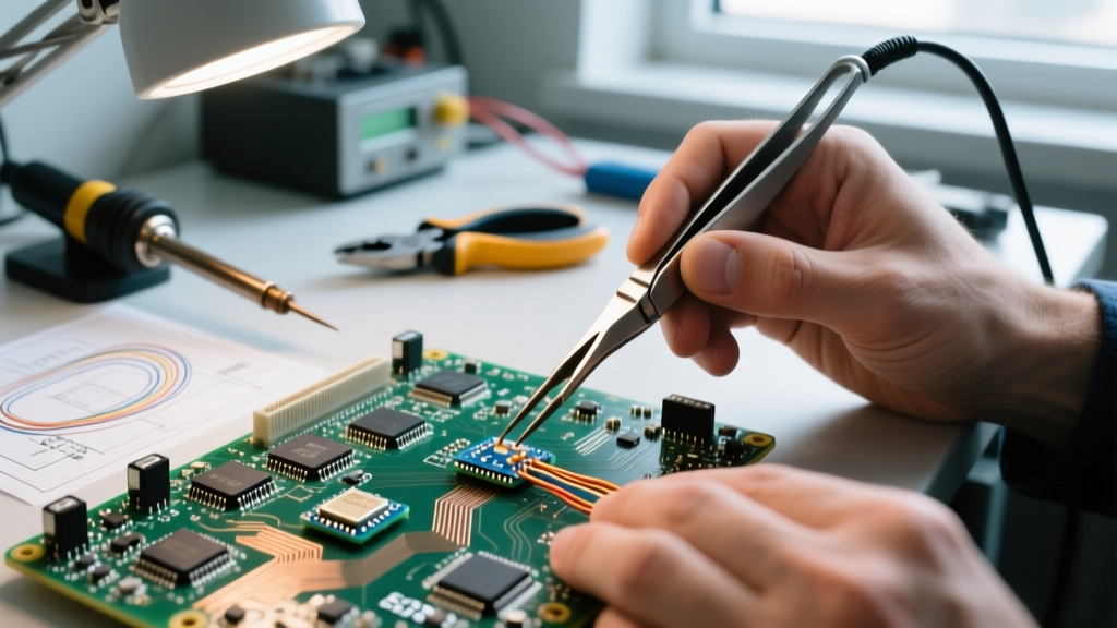
As surface-mount technology (SMT) continues to shrink toward 008004 (0.25mm x 0.125mm) metric packages in 2026, traditional rework methods have hit a physical wall. Hot air rework stations cause thermal collateral damage to adjacent micro-components, while standard single-point soldering irons lack the simultaneous dual-pad heating required for proper surface tension alignment. Enter the industrial soldering tweezer—a precision thermal tool that grips, aligns, and solders simultaneously. For production line managers and rework technicians in high-reliability sectors, selecting the correct soldering tweezer is no longer a matter of convenience; it is a strict requirement for yield maintenance and IPC compliance.
Industry Insight: In high-density interconnect (HDI) boards, a single-point iron requires sequential heating of pads, leading to uneven solder reflow and "tombstoning." A thermal soldering tweezer delivers simultaneous, symmetrical heat, ensuring the component self-aligns via molten solder surface tension.
Core Industrial Applications for Soldering Tweezers
Different industries leverage thermal tweezers to solve unique micro-assembly challenges. Understanding these applications is the first step in specifying the right equipment for your facility.
Aerospace and Defense: High-Density Interconnects (HDI)
In avionics and satellite telemetry boards, component density often exceeds 150 components per square inch. Reworking 01005 and 0201 capacitors or resistors in these clusters with hot air risks disturbing neighboring BGA underfills. A micro soldering tweezer with a 0.3mm tip profile allows technicians to target specific passive components without altering the thermal profile of the surrounding 0.5mm pitch QFNs (Quad Flat No-leads). Furthermore, aerospace wire-to-board terminations on micro-D-sub connectors rely heavily on tweezers to hold 30AWG Kynar-insulated wires in place while simultaneously reflowing the solder cup.
Medical Device Manufacturing: Implantables and Flex PCBs
Medical implantables, such as pacemakers and neurostimulators, utilize rigid-flex and polyimide flex circuits. These substrates are highly sensitive to prolonged thermal exposure; excessive heat causes delamination of the polyimide layers. Pulse-heat and precision thermal soldering tweezers with ultra-fast recovery times (under 1 second) allow operators to achieve full solder wetting in under two seconds, keeping the substrate temperature well below the 150°C glass transition threshold.
Telecommunications: Optical Transceiver Assembly
The assembly of TOSAs (Transmitter Optical Subassemblies) and ROSAs (Receiver Optical Subassemblies) requires soldering micro-coaxial cables and photodiode leads to ceramic substrates. These components are extremely fragile and sensitive to mechanical stress. A soldering tweezer equipped with soft-grip, spring-loaded handles provides the exact grams of force required to maintain electrical contact without crushing the microscopic semiconductor die.
2026 Industrial Soldering Tweezer Comparison Matrix
When outfitting a rework station, the handpiece is only half the equation; the thermal recovery rate and tip ecosystem dictate the true capability of the tool. Below is a comparison of the top-tier industrial soldering tweezer systems utilized in Class 3 manufacturing environments.
| System / Handpiece | Station Power | Tip Range & Profile | Thermal Recovery | 2026 Est. Price (Handpiece) |
|---|---|---|---|---|
| JBC Nano NT115-A | 40W (Nano Station) | 0.3mm - 2.5mm (C115 Series) | < 1 Second | $285 |
| Weller WXMT MS | 40W (WX1/WX2 Base) | 0.4mm - 3.0mm (RTWMS Series) | ~ 2 Seconds | $315 |
| Pace TD-200 | 120W (ADX/TD Base) | 0.5mm - 4.0mm (100 Series) | ~ 1.5 Seconds | $450 |
| Hakko FM-2032 | 50W (FX-951 Base) | 0.6mm - 3.0mm (T32 Series) | ~ 2 Seconds | $260 |
Note: Pricing reflects 2026 industrial distributor averages for the handpiece only. Base stations and tip cartridges are sold separately.
Overcoming Common Failure Modes in Thermal Tweezer Rework
Even with top-tier equipment, improper technique with a soldering tweezer will result in catastrophic board damage. Production engineers must train operators to avoid the following specific failure modes:
- Tombstoning (Drawbridging): Caused by uneven pressure on the tweezer handles. If the operator applies more downward force on the left tip than the right, the surface tension of the molten solder will pull the component upright. Solution: Utilize tweezers with ergonomic, balanced pivot points and train operators to use a "pinch" grip rather than a "squeeze" grip.
- Pad Lift and Trace Damage: Pressing the heated tips into the PCB pads to "force" heat transfer. Pads on HDI boards are typically only 18µm thick copper. Solution: Rely on the thermal conductivity of the flux and the iron-clad tips. The tips should kiss the component terminations, not the PCB pads.
- Thermal Shock to Ceramic Capacitors: MLCCs (Multi-Layer Ceramic Capacitors) are highly susceptible to micro-cracking from rapid, localized heating. Solution: Use a soldering tweezer with programmable ramp-up profiles (available on the JBC and Pace digital stations) to pre-heat the component at 150°C for 2 seconds before spiking to the 245°C reflow temperature.
Tip Metallurgy and Coating Selection
The physical tip of the soldering tweezer dictates wetting performance. In 2026, standard iron-plated copper tips have been largely superseded in high-reliability sectors by advanced metallurgy. For lead-free SAC305 (Sn96.5/Ag3.0/Cu0.5) alloys, tips with a Silver-Palladium (Ag/Pd) doping layer beneath the iron cladding resist tin-erosion significantly better. Furthermore, when reworking gold-plated RF boards, operators must use tips with specialized non-wetting coatings on the outer edges to prevent solder from climbing up the tweezer shaft, which causes bridging on 0.4mm pitch components.
Navigating IPC and NASA Workmanship Standards
Industrial applications demand strict adherence to accepted workmanship standards. When implementing a soldering tweezer process, quality assurance teams must align their Standard Operating Procedures (SOPs) with recognized frameworks.
According to the IPC J-STD-001 requirements for soldered electrical and electronic assemblies, the use of thermal tweezers for SMD rework is acceptable provided that the dwell time does not exceed the thermal limits of the component or the laminate. For Class 3 (High-Reliability) products, IPC mandates that solder fillets must exhibit continuous wetting on both terminations simultaneously—a feat that is nearly impossible to guarantee with a single-point iron on 0201 components without moving the part.
For aerospace and defense contractors, the NASA Workmanship Standards (specifically NASA-STD-8739.3) dictate rigorous criteria for wire termination and SMD attachment. The standard explicitly requires that when using thermal tweezers for micro-wire soldering, the insulation gap must be maintained, and the solder must not wick under the insulation. The precise temperature control of modern digital tweezers prevents the insulation from melting back, a common defect cited in NASA audit failures.
Verification and Inspection Protocols
- Automated Optical Inspection (AOI): Post-tweezer rework boards must pass 3D AOI to verify that component stand-off height has not been compromised by excessive tweezer pressure.
- X-Ray Analysis: For bottom-terminated components (BTCs) reworked with tweezers, X-ray is required to ensure no solder voiding occurred due to improper flux activation during the simultaneous heating process.
- Tip Calibration: Facilities must log weekly tip temperature verification using a K-type thermocouple analyzer to ensure the left and right tweezer tips are within 2°C of each other.
Final Verdict for Production Line Managers
The transition to micro-assembly dictates that the soldering tweezer is no longer a niche accessory, but a primary production tool. For facilities focusing on ultra-fine pitch passives and medical flex circuits, the JBC Nano NT115-A remains the undisputed leader in 2026 due to its sub-second thermal recovery and ultra-narrow tip profiles. For heavier industrial applications involving larger QFNs and shielded RF cans, the higher thermal mass of the Pace TD-200 provides the necessary Joule heating to overcome large ground planes. By matching the tool's thermal dynamics to your specific PCB architecture and adhering to IPC Class 3 dwell-time limits, you can eliminate rework-induced scrap and secure your production yields.